Dilated threaded fusion cage

A cage and expansion type technology, applied in the direction of prosthesis, fixator, internal fixator, etc., can solve the problems of lack of bone graft window, difficulty in fusion between cage and vertebral body, bone particle injection and other problems

Active Publication Date: 2014-07-30
SHANDONG GUANLONG MEDICAL UTENSILS
View PDF8 Cites 3 Cited by
  • Summary
  • Abstract
  • Description
  • Claims
  • Application Information

AI Technical Summary

Problems solved by technology

[0002] Vertebral body fusion devices are widely used in spinal surgery, and are mainly used for intervertebral space reconstruction in discectomy hands. In the prior art, the technical solution closest to this application is authorized by the Patent Office of the State Intellectual Property Office Application number is 201120350285.3, title: utility model patent of expansion type vertebral body fusion device, lacks bone grafting window in the technical scheme of this patent, it is difficult to inject bone particles into bone grafting during operation, so fusion device and vertebral body after operation Fusion is difficult, it is easy to become a foreign body in the body, and there is a certain risk of surgery, which is the deficiency of the existing technology

Method used


Image

  • Dilated threaded fusion cage
  • Dilated threaded fusion cage
  • Dilated threaded fusion cage

Examples


Embodiment Construction

[0011] In order to clearly illustrate the technical features of the solution, the solution will be described below through a specific implementation mode combined with the accompanying drawings.

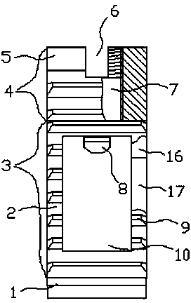
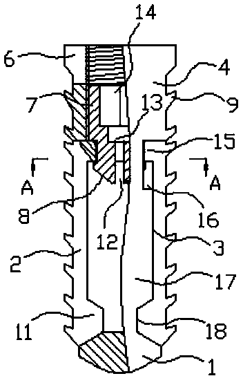
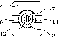
[0012] As can be seen from the accompanying drawings, the expansion type vertebral body fusion device of this program has a fusion body 5 and a push rod 7 that is axially threaded with the fusion body 5 in the fusion body 5, and the vertical projection of the fusion body 5 described in this program It is a rectangle with chamfered corners. The upper part of the fusion body 5 is the base 4 , the lower part is the head 1 , and between the base 4 and the head 1 is an integrated structure of the inverted tooth part 3 . There is a threaded hole along the axis in the base 4, and the push rod 7 is in the threaded hole and is connected by a matching screw thread. There is also a base through groove 6 on the top surface of the base 4 of the fusion body 5. , the role of the base through groove...


PUM


Abstract

The invention provides a dilated threaded fusion cage. The dilated threaded fusion cage comprises a fusion body and a push rod which is in axial threaded connection with the fusion body in the fusion body; the vertical projection of the fusion body is a rectangle with a chamfer; the upper part of the fusion body is a base and the lower part of the fusion body is a head; an integral structure of a pawl part is arranged between the base and the head; the pawl part consists of a left pawl part side wall and a right pawl part side wall and is connected with an n-shaped pawl frame; tops of the two pawl part side walls are provided with pawl frame chutes, and joints between the two pawl part side walls and the head are provided with side wall trapezoidal grooves; the bottom surface of the head is arc; a chuck hole is formed in a pawl frame top surface; pawls and corresponding pawl frame holes are formed on the outer sides of two side walls of the pawl frame; bottoms ends of the two side walls of the pawl frame are provided with pawl frame heads matched with the side wall trapezoidal grooves in the pawl part side walls; a push rod chuck is arranged on the lower part of the push rod; the chuck hole of the pawl frame is arranged in the push rod chuck; a chuck straight slot is formed in the push rod chuck; the push rod is provided with a push rod axial hole along the axis of the push rod to be connected with the chuck straight slot.

Description

technical field [0001] The invention relates to a medical operation instrument, in particular to an expansion type vertebral body fusion device used for thoracolumbar posterior operation. Background technique [0002] Vertebral body fusion devices are widely used in spinal surgery, and are mainly used for intervertebral space reconstruction in discectomy hands. In the prior art, the technical solution closest to this application is authorized by the Patent Office of the State Intellectual Property Office Application number is 201120350285.3, title: utility model patent of expansion type vertebral body fusion device, lacks bone grafting window in the technical scheme of this patent, it is difficult to inject bone particles into bone grafting during operation, so fusion device and vertebral body after operation Fusion is difficult, it is easy to become a foreign body in the body, and there is a certain risk of surgery, which is the deficiency of the existing technology. Cont...

Claims


Application Information

Patent Timeline
IPC IPC(8): A61B17/70A61F2/44
CPCA61B17/7061A61B17/7094A61B17/7097A61F2/442A61F2/30744A61F2/44A61F2/4455A61F2/447A61F2002/30001A61F2002/305A61F2002/30593A61F2002/30904A61F2310/00023
Inventor 申维波郝在晨路雪城赵天明
Owner SHANDONG GUANLONG MEDICAL UTENSILS
Why Eureka
Try Eureka