Eureka AIR delivers breakthrough ideas for toughest innovation challenges, trusted by R&D personnel around the world.

Interference debugging method for terminal LCD bright screen

A debugging method and terminal technology, applied in the direction of transmission monitoring, instruments, electrical components, etc., can solve the problems of cumbersome operation, time-consuming and laborious, etc., and achieve the effect of optimizing the electromagnetic environment, reducing the number of debugging, and reducing mutual interference

Active Publication Date: 2014-07-23
SHANGHAI QUJIE INFORMATION TECH CO LTD
View PDF5 Cites 23 Cited by
  • Summary
  • Abstract
  • Description
  • Claims
  • Application Information

AI Technical Summary

Problems solved by technology

Another way to solve electromagnetic interference is to adjust the LCD clock rate so that the high-order harmonics of the LCD clock signal fall outside the RF receiving frequency band. The specific method is to gradually adjust the LCD clock frequency. Full-channel test to determine the best LCD clock frequency without electromagnetic interference. This anti-interference debugging method is effective, but the actual operation is cumbersome and time-consuming.

Method used


Image

  • Interference debugging method for terminal LCD bright screen
  • Interference debugging method for terminal LCD bright screen
  • Interference debugging method for terminal LCD bright screen

Examples


Embodiment Construction

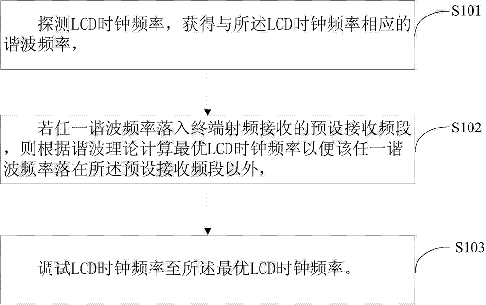
[0028] In order to make the technical problems solved by the present invention, the technical solutions adopted and the technical effects achieved clearer, the technical solutions of the embodiments of the present invention will be further described in detail below in conjunction with the accompanying drawings. Obviously, the described embodiments are only the technical solutions of the present invention. Some, but not all, embodiments. Based on the embodiments of the present invention, all other embodiments obtained by those skilled in the art without creative efforts fall within the protection scope of the present invention.

[0029] Please refer to figure 1 , which is a method flowchart of the first embodiment of the terminal LCD bright screen interference debugging method provided by the present invention. The terminal LCD bright screen interference debugging method of the embodiment of the present invention can be applied to various terminal devices equipped with LCD scr...


PUM


Abstract

The invention relates to the technical field of the terminal LCD (Liquid Crystal Display) screens and in particular relates to an interference debugging method for a terminal LCD bright screen. The interference debugging method comprises detecting an LCD clock frequency and obtaining a harmonic frequency corresponding to the LCD clock frequency, and if any harmonic frequency falls into a preset receiving frequency band of radio-frequency receiving of a terminal, calculating the optimal LCD clock frequency according to the harmonic theory so that the any harmonic frequency falls beyond the preset receiving frequency band and adjusting the LCD clock frequency to the optimal LCD clock frequency. The debugging method is capable of quickly obtaining the position relationship of the harmonic frequency corresponding to the LCD clock frequency to the radio-frequency receiving frequency band of the terminal, and obtaining the optimal LCD clock frequency enabling the harmonic frequency to fall beyond the preset receiving frequency band by virtue of simple calculation, and therefore, the debugging time of the interference of the terminal LCD bright screen is greatly shortened, an electromagnetic environment is effectively optimized and mutual interference phenomena are reduced.

Description

technical field [0001] The present invention relates to the technical field of LCD display screens of terminals, in particular to a debugging method for bright screen interference of terminal LCDs. Background technique [0002] Currently, smart terminals on the market usually support multi-mode, multi-frequency and add functions such as GPS positioning in order to meet diversified needs and improve competitiveness. The higher the frequency, the already narrow terminal space has to face the complex and changeable electromagnetic environment, so some mutual interference phenomena inevitably appear. For example: when the LCD screen is on, the harmonic frequency of the clock signal of the LCD screen will sometimes just fall in the GSM850 / 900 / 1800 / 1900MHZ frequency band of the terminal's radio frequency reception, thereby interfering with the terminal's sensitivity to radio frequency reception, and in severe cases, nearly 20dBm The interference will greatly affect the radio freq...

Claims


Application Information

Patent Timeline
Patent Type & Authority Applications(China)
IPC IPC(8): H04B17/00H04M1/725G09G3/36
Inventor 曲良玉朱占伟常远政范楷
Owner SHANGHAI QUJIE INFORMATION TECH CO LTD
Why Eureka
Eureka Blog
Learn More