
Ground resistance measuring equipment and measuring method for large transformer substation

A technology for grounding resistance and measuring device, applied in the field of electric power, can solve the problems of complicated test process, increased neutral point voltage offset, corrosion of grounding device, etc., to achieve the effect of simple device structure and operation, and improved accuracy

Inactive Publication Date: 2014-07-23
STATE GRID CORP OF CHINA +1
View PDF5 Cites 3 Cited by
  • Summary
  • Abstract
  • Description
  • Claims
  • Application Information

AI Technical Summary

Problems solved by technology

When the grounding resistance is too large and a grounding fault occurs, the neutral point voltage offset will increase, and it is very likely that the sound phase and neutral point voltage will be too high, exceeding the level required for insulation and causing equipment damage; it is also directly related to Personal safety of substation operating personnel and substation maintenance personnel; but because the soil has a corrosive effect on the grounding device, as the operating time increases, the grounding device will corrode, which will affect the safe operation of the substation; therefore, it is necessary to strengthen the grounding of the grounding grid. Regular monitoring of resistance
[0003] In the prior art, the general grounding resistance measurement device cannot accurately measure the grounding resistance due to the interference of stray current and stray voltage in the ground network during the test. The process is complicated, and the test personnel work intensively, and problems such as stray current and voltage interference in the power grid cannot be ruled out

Method used


Image

  • Ground resistance measuring equipment and measuring method for large transformer substation

Examples


Embodiment Construction

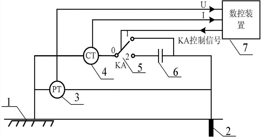
[0016] The device and method for measuring grounding resistance of a large substation provided by the present invention will be described in detail below in conjunction with the accompanying drawings and specific embodiments.

[0017] The specific embodiments described here are only used to explain the present invention, not to limit the present invention.

[0018] Such as figure 1 As shown, the large substation grounding resistance measuring device provided by the present invention includes: current pole 2, voltage transformer 3, current transformer 4, controllable switch KA5, test power supply 6 and numerical control device 7; wherein: current pole 2 is for testing The grounding electrode is installed at a distance of 0-50M from the measured point; one end of the primary side of the voltage transformer 3 is connected to the ground grid 1 under test, and the other end is connected to the current pole 2; the ground grid 1 under test, the voltage transformer 3 and the current p...


PUM


Abstract

The invention discloses ground resistance measuring equipment and a ground resistance measuring method for a large transformer substation. The device comprises a current electrode, a voltage transformer, a current transformer, a controllable switch KA, a test power supply and a numerical control device. The ground resistance measuring equipment and the ground resistance measuring method for the large transformer substation provided by the invention have the technical effects that ground resistance measuring equipment of a controllable switch is additionally arranged in a current measurement loop, and the device can realize measuring ground stray current and stray voltage, so that the interference of stray current values and stray voltage values can be excluded when the ground resistance is measured, and the accuracy for measuring the ground resistance can be improved; in addition, the device is simple in structure and easy to operate, and a measuring value is not needed to be corrected repeatedly in the process of measuring.

Description

technical field [0001] The invention belongs to the technical field of electric power, and in particular relates to a large substation grounding resistance measuring device and a measuring method. Background technique [0002] With the development of the power system, the grounding short-circuit current is getting bigger and bigger, and the requirements for the grounding of the power equipment are getting higher and higher. With the technological progress of the power system, especially the large-scale use of compact and miniaturized equipment, the proportion of the substation The ground area is getting smaller and smaller, so the grounding resistance of the substation is also required to be smaller and smaller. When the grounding resistance is too large and a grounding fault occurs, the neutral point voltage offset will increase, and it is very likely that the sound phase and neutral point voltage will be too high, exceeding the level required for insulation and causing equ...

Claims


Application Information

Patent Timeline
IPC IPC(8): G01R27/20
Inventor 周瑞智高伟余菊芳齐英王继祥牛晓昕杨朔董乃坤
Owner STATE GRID CORP OF CHINA
Learn More