
Integrated deep domestic sewage treatment facility and sewage treatment method thereof

A sewage treatment method and technology for domestic sewage, applied in the field of environmental protection, can solve the problems of low dephosphorization and denitrification removal rate, complicated operation and maintenance, and high effluent quality, and achieve the effects of high effluent quality, low energy consumption, and stable effluent quality.

Active Publication Date: 2014-07-23
SHANDONG SHANDA WIT ENVIRONMENTAL ENGINEERING CO LTD
View PDF2 Cites 11 Cited by
  • Summary
  • Abstract
  • Description
  • Claims
  • Application Information

AI Technical Summary

Problems solved by technology

[0008] The present invention aims at the disadvantages of large floor area, high energy consumption, large sludge production, complicated operation and maintenance, and low removal rate of dephosphorization and nitrogen removal in domestic sewage, and provides a sewage treatment system with small floor area, low energy consumption, and high effluent quality. High-efficiency, low-sludge integrated deep domestic sewage treatment equipment and its sewage treatment method

Method used


Image

  • Integrated deep domestic sewage treatment facility and sewage treatment method thereof
  • Integrated deep domestic sewage treatment facility and sewage treatment method thereof
  • Integrated deep domestic sewage treatment facility and sewage treatment method thereof

Examples


Embodiment Construction

[0036] The present invention is described in detail below in conjunction with accompanying drawing:

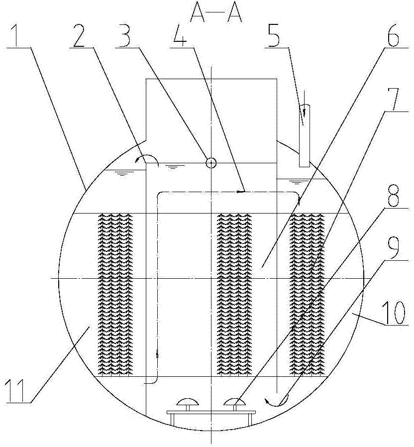
[0037] Such as figure 1 , 2 As shown, the middle part of the integrated tank body 1 is an aerobic biochemical zone 6, and the two sides are respectively an anaerobic biochemical zone 10 and anoxic biochemical zone 11, and fillers 7 are arranged in the anaerobic biochemical zone 10 and anoxic biochemical zone 11 , to increase the sludge concentration and biochemical contact area, the tank body 1 is provided with the first water inlet pipe 5 communicating with the anaerobic biochemical zone 10 inside it; the aerator 8 is installed at the bottom of the aerobic biochemical zone 6 to supply the water body oxygen.

[0038] Only the bottom communicates between the anaerobic biochemical zone 10 and the aerobic biochemical zone 6, the top liquid level of the aerobic biochemical zone 6 is higher than the top liquid level of the anoxic biochemical zone 11, and the top of the aerobic bioc...


PUM

PropertyMeasurementUnit
particle diameteraaaaaaaaaa

Abstract

The invention discloses an integrated deep domestic sewage treatment facility which comprises a tank body, and an anoxic biochemical region, an aerobic biochemical region and an anaerobic biochemical region which are respectively distributed on the left, in the middle and on the right of the cross section of the tank body, wherein the anaerobic biochemical region and the aerobic biochemical region are communicated with each other only through the bottoms; the top liquid level of the aerobic biochemical region is higher than the top liquid level of the anoxic biochemical region; the top of the aerobic biochemical region is provided with a water outlet pipe extending into the aerobic biochemical region, and an overflow weir communicated with the anoxic biochemical region; the upper part liquid level of the anoxic biochemical region is higher than the upper part liquid level of the anaerobic biochemical region; the bottom of the anoxic biochemical region is communicated with the upper part of the anaerobic biochemical region through a gravity pipeline; the tank body is provided with a water inlet pipe communicated with the anaerobic biochemical region; the bottom of the aerobic biochemical region is provided with an aerator; the top of the aerobic biochemical region is provided with a biochemical water outlet and a precipitation tank water inlet pipe which are communicated to a precipitation tank; the precipitation tank is communicated with a sand filter tank through a sand filtration lifting water pump mechanism; and a back flush dynamic drift sand filter is arranged in the sand filter tank. The invention also discloses a sewage treatment method using the facility.

Description

technical field [0001] The invention belongs to the field of environmental protection, and specifically relates to a method and sewage treatment equipment for treating domestic sewage by anoxic-anaerobic-aerobic-sedimentation-filtering. Background technique [0002] Domestic sewage contains a large amount of organic matter, as well as various viruses, bacteria and parasite eggs, as well as inorganic salts such as chlorides, sulfates, phosphates, etc., which can easily produce stench and pollute the environment, which is harmful to the human body and various animals. Plants are extremely harmful, so they need harmless treatment. [0003] At present, domestic sewage mostly adopts the method of primary pretreatment and secondary biochemical treatment, wherein secondary biochemical treatment includes activated sludge treatment process and biofilm treatment process, mainly including biological contact oxidation, SBR method, oxidation ditch method, A / O method, etc., the commonly...

Claims


Application Information

Patent Timeline
Patent Type & Authority Applications(China)
IPC IPC(8): C02F3/30
Inventor 吕世鹏史传贵戴振国周少利孙国鹏徐恒春孟庆海杨秀丽
Owner SHANDONG SHANDA WIT ENVIRONMENTAL ENGINEERING CO LTD
Learn More