
Sheath vibrator

A vibrator and sheath technology, applied in the direction of the fluid using vibration, can solve the problems of rigid position, smooth realization, poor efficiency of vibration equipment, etc., and achieve the effect of simple positioning, positioning accuracy and quality assurance.

Inactive Publication Date: 2014-07-23
CHONGQING UNIV
View PDF3 Cites 1 Cited by
  • Summary
  • Abstract
  • Description
  • Claims
  • Application Information

AI Technical Summary

Problems solved by technology

The vibrator equipment in the prior art has defects such as low degree of automation, rigid position, rough operation, and severe mechanical wear; however, the current rotary equipment often has the torsion of the worn mechanical equipment when it is linked with the cylinder, and at the same time, it is in the initial position of the rotation. There are also problems in grasping the accuracy of the final position and the final position. The ideal vibration and rotation functions in the industry cannot be realized, resulting in poor efficiency and difficult control of the existing vibration equipment, which seriously affects the smooth realization of the entire process.
Therefore, there are many defects in the current vibrator equipment, which is not conducive to the smooth realization of the vibration function, and it is necessary to improve the existing vibration equipment

Method used


Image

  • Sheath vibrator
  • Sheath vibrator

Examples


Embodiment Construction

[0021] Hereinafter, preferred embodiments of the present invention will be described in detail with reference to the accompanying drawings. It should be understood that the preferred embodiments are only for illustrating the present invention, but not for limiting the protection scope of the present invention.

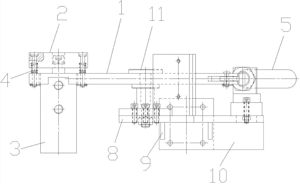
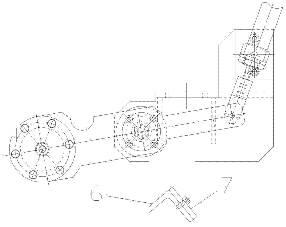
[0022] As shown in the figure, a sheathed vibrator includes a vibrator installation platform, a vibrating table device, a rocker arm 1 and a rocker arm driving device for pulling the rocker arm to make a rotary motion, and the vibrating table device is arranged on the rocker arm One end, the other end of the rocking arm is connected with the rocking arm driving device, the rocking arm is arranged on the vibrator installation platform through the rocking arm rotating shaft 11, and the rocking arm driving device is rotatably arranged on the vibrator installation platform, The vibrator installation platform is also provided with a rocker arm limit mechanism.

[0023] In ...


PUM


Abstract

The invention discloses a sheath vibrator which comprises a vibrator installing platform, a vibration table device, a rocker arm and a rocker arm driving device for drawing the rocker arm to perform rotary motion. The vibration table device is arranged at one end of the rocker arm, the other end of the rocker arm is connected with the rocker arm driving device, the rocker arm is arranged on the vibrator installing platform through a rocker arm rotating shaft, the rocker arm driving device can rotatably arranged on the vibrator installing platform, and a rocker arm limiting mechanism is further arranged on the vibrator installing platform. The sheath vibrator ensures the flexible positioning and vibrating effect of a vibration table and meanwhile avoids mechanical device abrasion caused by contact vibration.

Description

technical field [0001] The invention belongs to the field of vibrator equipment, in particular to a sheath vibrator. Background technique [0002] The main purpose of the vibrator equipment is to realize the vibration and accurate positioning function of the vibrator under the condition of ensuring the safety of equipment and personnel. The vibrator equipment in the prior art has defects such as low degree of automation, rigid position, rough operation, and severe mechanical wear; however, the current rotary equipment often has the torsion of the worn mechanical equipment when it is linked with the cylinder, and at the same time, it is in the initial position of the rotation. There are also problems in grasping the accuracy of the final position and the final position. The ideal vibration and rotation functions in the industry cannot be realized, resulting in poor efficiency and difficult control of the existing vibration equipment, which seriously affects the smooth realiza...

Claims


Application Information

Patent Timeline
Patent Type & Authority Applications(China)
IPC IPC(8): B06B1/18
Inventor 林景栋韩冲林湛丁林秋阳谢杨徐春慧邱欣马宁
Owner CHONGQING UNIV
Learn More