Torque converter

A technology for torque converters and gearboxes, which is applied in the direction of fluid transmission devices, belts/chains/gears, mechanical equipment, etc., to achieve the effects of increasing the flow channel area, smooth flow, and increasing capacity coefficient

Active Publication Date: 2014-07-16
EXEDY CORP
View PDF6 Cites 0 Cited by
  • Summary
  • Abstract
  • Description
  • Claims
  • Application Information

AI Technical Summary

Problems solved by technology

In order to achieve the above, it is necessary to increase the size of the torque converter

Method used


Image

  • Torque converter
  • Torque converter
  • Torque converter

Examples


Embodiment Construction

[0025] [Basic structure of torque converter]

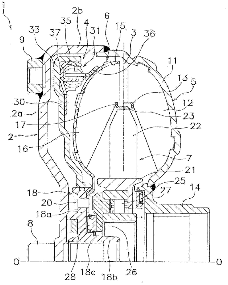
[0026] figure 1 The illustrated torque converter 1 is a device for transmitting power from a crankshaft (not shown) of an engine to an input shaft (not shown) of a transmission. figure 1 The left side is equipped with an engine not shown in the figure, figure 1 The right side is equipped with a gearbox not shown in the figure. figure 1 The O-O line shown is the axis of rotation of the torque converter 1 .

[0027] Such as figure 1 As shown, the torque converter 1 is composed of a front cover 2 , a torque converter main body 3 and a locking device 4 . The torque converter body 3 has an impeller 5 , a turbine 6 , and a stator 7 .

[0028] The front cover 2 has a disc portion 2a and an outer peripheral cylindrical portion 2b. A center hub 8 extending toward the engine side is fixed to the inner peripheral portion of the disc portion 2a. Also, on the engine side of the outer peripheral portion of the circular plate 2a, a plural...


PUM


Abstract

The present invention makes it possible, in a torque converter, to increase the cross-sectional area of a flow path for hydraulic oil, and also to minimize the occurrence of hydraulic oil, having flowed out from an impeller, being drawn into the impeller. In the torque converter, an impeller core (13) has a first projecting part (132b) that projects axially out from the outlet-side edge (12a) of an impeller blade (12). A turbine core (17) has a second projecting part (172) that projects axially outward from the inlet-side edge (16a) of a turbine blade (16). The second projecting part (172) is positioned on the inner peripheral side of the first projecting part (132b) and extends at least to the distal end of the first projecting part (132b).

Description

technical field [0001] The present invention relates to a torque converter that transmits torque from an engine to a transmission through working oil. Background technique [0002] A torque converter includes a front cover, an impeller, a turbine, and a stator. After the torque from the engine is transmitted to the front cover, the torque transmitted to the front cover is transmitted to the impeller. When the torque is transmitted to the impeller, the impeller rotates, the working oil moves toward the turbine side, and the turbine is rotated by the working oil moved to the turbine side. At this time, torque is transmitted from the turbine to the shaft on the transmission side, causing the shaft on the transmission side to rotate. Furthermore, the turbine-side operating oil returns to the impeller side via the stator. [0003] In such a torque converter, when the torque input from the engine is large, it is necessary to increase the capacity coefficient while increasing th...

Claims


Application Information

Patent Timeline
Patent Type & Authority Applications(China)
IPC IPC(8): F16H41/26
CPCF16H41/26F16H47/06
Inventor 福永孝夫
Owner EXEDY CORP
Why Eureka
Try Eureka