Forward and reverse current single loop detection device based on can network

A detection device and a single-loop technology, which is applied in the direction of measuring devices, current indication direction, and measurement of current/voltage, etc., can solve the problems that the negative current value of the meter cannot be directly obtained and the state of the meter is difficult to detect.

Active Publication Date: 2017-03-29
AEROSPACE HI TECH HLDG GROUP
View PDF6 Cites 0 Cited by
  • Summary
  • Abstract
  • Description
  • Claims
  • Application Information

AI Technical Summary

Problems solved by technology

[0004] The purpose of the present invention is to solve the problem that the existing meter state detection device cannot directly obtain the negative current value output by the meter, which makes the state detection of the meter difficult, and provides a positive and negative current single-loop detection device based on CAN network

Method used


Image

  • Forward and reverse current single loop detection device based on can network
  • Forward and reverse current single loop detection device based on can network
  • Forward and reverse current single loop detection device based on can network

Examples


specific Embodiment approach 1

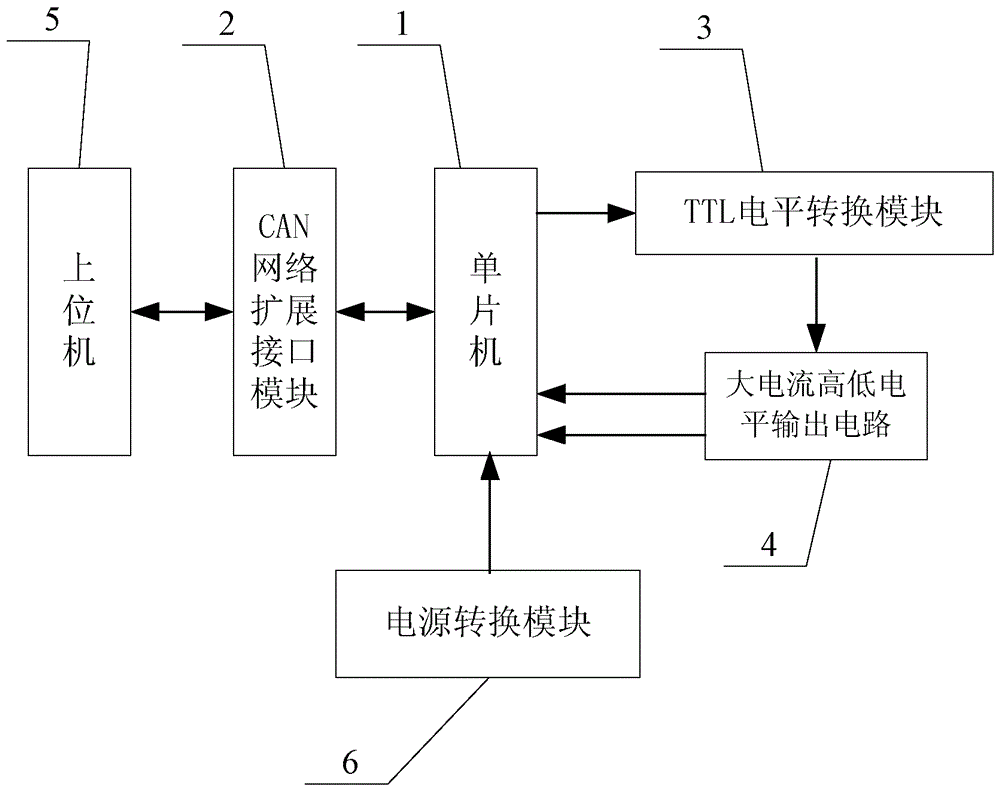
[0027] Specific implementation mode one: the following combination Figure 1 to Figure 6 Describe this embodiment, the forward and reverse current single-loop detection device based on CAN network described in this embodiment, it includes single-chip microcomputer 1 and CAN network expansion interface module 2, it also includes TTL level conversion module 3, large current high and low level output circuit 4 and host computer 5,

[0028] The upper computer 5 is used to send control instructions, and is also used to receive the finally obtained instrument current detection signal;

[0029] The CAN network expansion interface module 2 is used to receive the control command of the host computer 5 and transmit the control command to the single-chip microcomputer 1, and is also used to transmit the finally obtained instrument current detection signal to the host computer 5;

[0030] The single-chip microcomputer 1 is used to process the received control command of the upper compute...

specific Embodiment approach 2

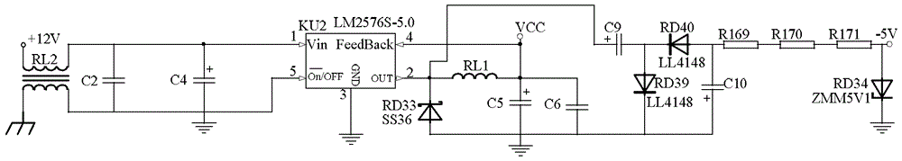
[0033] Specific implementation mode two: the following combination figure 1 This embodiment will be described. This embodiment will further describe Embodiment 1. This embodiment also includes a power conversion module 6 , which is used to provide working power for the single-chip microcomputer 1 .

specific Embodiment approach 3

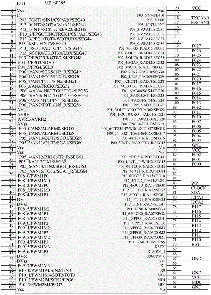
[0034] Specific implementation mode three: the following combination Figure 1 to Figure 6 Describe this embodiment, this embodiment will further illustrate embodiment one or two, the model of single-chip microcomputer 1 described in this embodiment is MB96F385,

[0035] The CANL0 terminal and the CANH0 terminal of the CAN network expansion interface module 2 are used to connect with the upper computer 5, the RXCAN0 terminal of the CAN network expansion interface module 2 is connected to the 117 pin of the microcontroller 1, and the TXCAN0 terminal of the CAN network expansion interface module 2 Connect to pin 118 of MCU 1;

[0036] TTL level conversion module 3 is composed of Darlington tube driver ULN2803 and pull-up resistor RS2,

[0037] Pin 87 of microcontroller 1 is connected to pin 1 of Darlington tube driver ULN2803, pin 88 of microcontroller 1 is connected to pin 2 of Darlington tube driver ULN2803, pin 18 of Darlington tube driver ULN2803 is connected to a pull-up r...


PUM


Abstract

The invention discloses a forward and reverse current single-circuit detection device based on a CAN, and belongs to the technical field of current detection of meters. The forward and reverse current single-circuit detection device based on the CAN is used for solving the problem that an existing meter state detection device cannot directly obtain a reverse current value output by a meter, so that difficulty of state detection of the meter is high. According to the forward and reverse current single-circuit detection device based on the CAN, an upper computer is used for sending control instructions or receiving a meter current detection signal which is finally obtained, a CAN extension interface module is used for communication between the upper computer and a single-chip microcomputer, the single-chip microcomputer is used for processing received signals, a TTL level conversion module is used for converting received TTL level signals, and a high-current high-and-low level output circuit is used for sampling voltage signals output by a meter to be detected, directly transmitting obtained sampling signals of the meter to be detected to the single-chip microcomputer, and outputting voltage regulation signals to the single-chip microcomputer. The forward and reverse current single-circuit detection device based on the CAN is used for forward and reverse current single-circuit detection of the meter.

Description

technical field [0001] The invention relates to a forward and reverse current single-loop detection device based on a CAN network, and belongs to the technical field of instrument current detection. Background technique [0002] In the signal detection process of the instrument, it is often necessary to detect its current signal to judge whether the state of its printed board is qualified. Therefore, the detection device generally needs to provide two signals, high and low, to the instrument to obtain the corresponding signal at the output point of the instrument. positive and negative currents. When measuring the instrument, the positive current can be directly obtained, and the reverse current needs to be switched to positive current measurement, which increases the difficulty of measurement. [0003] To judge whether the output current signal meets the requirements through the same measurement point of the instrument, the testing equipment is required to output both high...

Claims


Application Information

Patent Timeline
Patent Type & Authority Patents(China)
IPC IPC(8): G01R19/00G01R19/14
Inventor 胡伟王胜劲滕胜广魏丽娜孙敬武杨茜臧军望佟大龙
Owner AEROSPACE HI TECH HLDG GROUP
Why Eureka
Try Eureka