A rotary led spotlight and its assembly method

A LED spotlight, rotating technology, applied in lighting devices, fixed lighting devices, lighting auxiliary devices, etc., can solve the problems of LED spotlights such as poor heat dissipation performance, complicated assembly process, and limited use occasions, and achieve safe and reliable connection strength , good heat dissipation performance, and the effect of reducing the cost of the whole lamp

Active Publication Date: 2016-02-24
HENGDIAN GRP TOSPO LIGHTING
View PDF1 Cites 0 Cited by
  • Summary
  • Abstract
  • Description
  • Claims
  • Application Information

AI Technical Summary

Problems solved by technology

[0003] 1. To a certain extent, the use of LED spotlights is limited, and the applicability is poor;
[0004] 2. The structure is relatively complicated, the manufacturing cost is too high, and the cost performance is low;
[0005] 3. The heat dissipation performance of LED spotlights is poor and the service life is short;
[0006] 4. The assembly process is complicated and the maintenance is inconvenient

Method used


Image

  • A rotary led spotlight and its assembly method
  • A rotary led spotlight and its assembly method
  • A rotary led spotlight and its assembly method

Examples


Embodiment 1

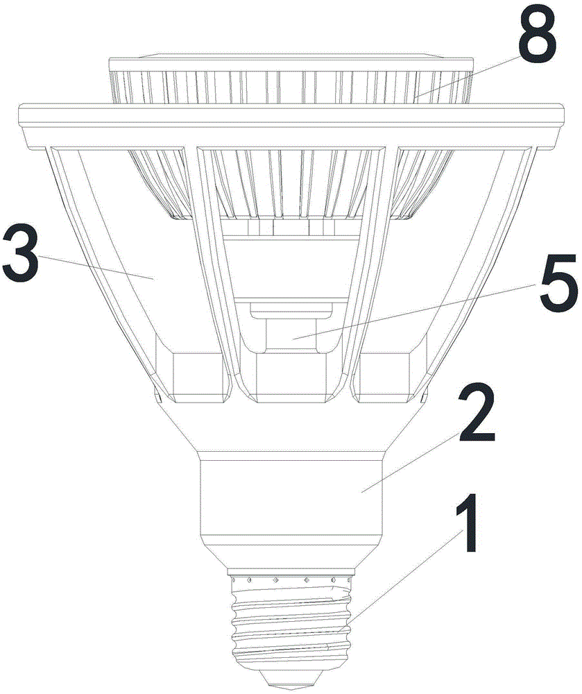
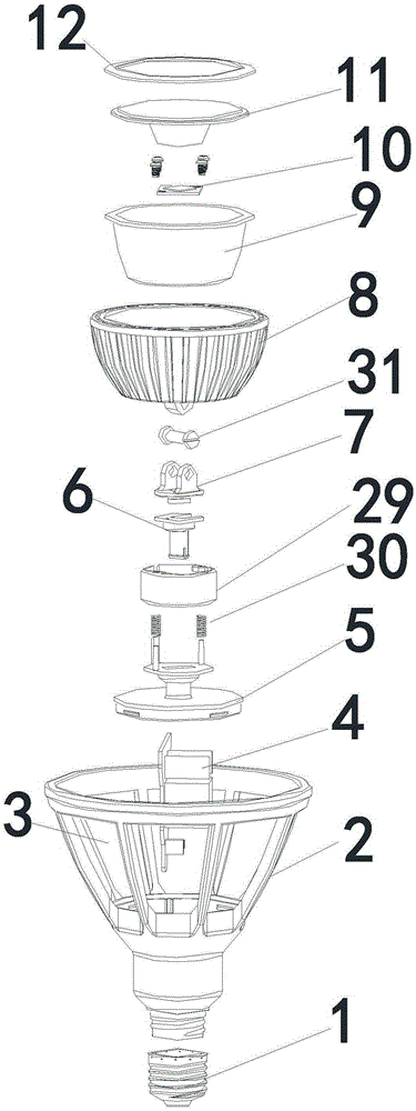
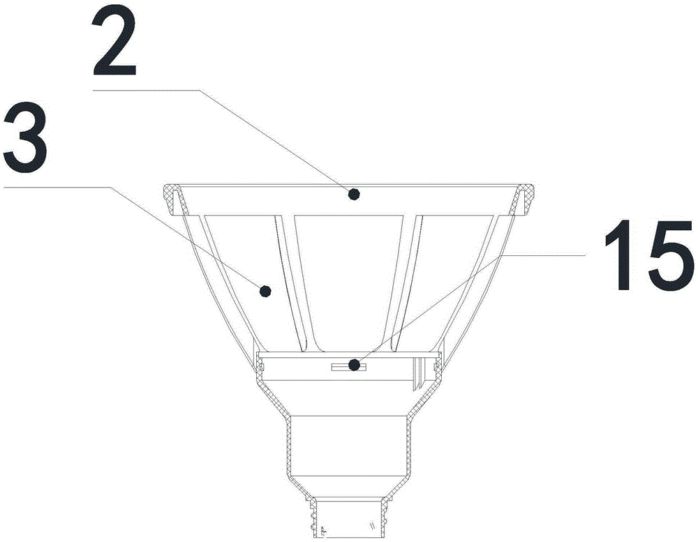
[0048] Such as Figure 1~4 As shown in 7-8, a rotary LED spotlight includes a lamp base 1, the upper end of the lamp base 1 is connected to an insulating shell 2, and a plurality of ventilation slots 3 are arranged on the insulating shell 2, and the ventilation slots 3 are arranged in a large area, and the ventilation slots 3 are convectively arranged. , the drive circuit board 4 is arranged in the insulating shell 2, the inner side of the insulating shell 2 is connected with the connecting column 5, the top of the connecting column 5 is connected with the fixed disk 6, the fixed disk 6 is connected with the rotating disk 7 whose axial rotation angle is 360°, and the rotating disk 7. The top and the heat dissipation shell 8 are movable connections with the central axis rotating at a certain angle. The heat dissipation shell 8 is provided with a reflector 9 and an LED light source 10. The LED light source 10 in this embodiment is mounted on an aluminum substrate.

[0049] This ...

Embodiment 2

[0064] Such as Figure 5-6 As shown, the difference between this embodiment and Embodiment 1 is that: the inner surface of the second connecting column body 16 in this embodiment is provided with a connecting column clamping groove 23, and the fixed plate 6 includes a cylindrical first body 17 of the fixed plate. The lower end of the fixed disk first body 17 is provided with a fixed disk buckle 24, and the fixed disk buckle 24 is snapped into the connecting post slot 23, and the upper end of the cylindrical fixed disk first body 17 is provided with a cylindrical fixed disk second body. A notch 18 is provided on the second body of the cylindrical fixed disk, and a positioning bump 25 is arranged on the second body of the cylindrical fixed disk.

[0065] The rotating disc 7 in this embodiment includes a boss 19, a rotating disc plate 20 and a fixed bracket 21; wherein, the lower surface of the rotating disc plate 20 is provided with a boss 19, and the upper surface of the rotati...


PUM


Abstract

The invention discloses a rotating-type LED spot lamp which comprises a lamp holder. The upper end of the lamp holder is connected with an insulation shell. A plurality of ventilation grooves are formed in the insulation shell and arranged in a convection mode. The insulation shell is internally provided with a driving circuit board. The inner side of the insulation shell is connected with a connecting pin. The top of the connecting pin is connected with a fixed disc. The fixed disc is connected with a rotating disc with the axial rotating angle of 360 degrees. The top of the rotating disc is movably connected with a radiating shell. The radiating shell is internally provided with a reflection cup and an LED light source. The invention further discloses an assembling method of the rotating-type LED spot lamp. The rotating-type LED spot lamp has the advantages of being simple in structure, low in manufacturing cost, capable of freely adjusting the light-emitting angle, good in radiating performance, convenient to assemble and maintain, and the like.

Description

technical field [0001] The invention relates to LED lamp technology, in particular to a rotary LED spotlight and an assembly method thereof. Background technique [0002] In the current LED lighting industry, the existing LED spotlights are all directional illumination, and it is difficult to change the starting angle. The most conventional structure is basically an integrated design that uses LED light sources, constant current or constant voltage drivers, optical lenses, reflectors, and metal or other radiator shells with high thermal conductivity. It can only achieve a single direction. The output angle of the light, or the need to use the rotatable lamps to realize the function of changing the starting angle. Such as the Chinese patent, publication number: CN102192439A, a LED spotlight, including a slide rail and a lamp head assembly, at least 2 conductive strips in the slide rail, the light bar assembly includes a lamp head, a rotating structure and a lamp holder, and ...

Claims


Application Information

Patent Timeline
Patent Type & Authority Patents(China)
IPC IPC(8): F21S8/00F21V29/507F21V29/83F21V17/00F21V17/16F21V17/12F21V21/30F21V14/02F21Y101/00F21V29/77
Inventor 赵权药左红付文华王明
Owner HENGDIAN GRP TOSPO LIGHTING
Why Eureka
Try Eureka