
Compression ratio adjustable engine suitable for arbitrary crank overlap without destroying the crankshaft structure

An engine and overlap technology, applied in the direction of engine control, machine/engine, mechanical equipment, etc., can solve the problems of reduced crank overlap, reduced torsional stiffness of transmission parts, increased accelerated wear, etc. The effect of reliable load capacity and strong gear load capacity

Active Publication Date: 2016-06-29
TIANJIN UNIV
View PDF7 Cites 0 Cited by
  • Summary
  • Abstract
  • Description
  • Claims
  • Application Information

AI Technical Summary

Problems solved by technology

Although the above technology does not need to greatly change the crankshaft structure, its disadvantages lie in the accelerated wear caused by the addition of internal gears that are not suitable for mass production and the unreasonable design of the gear direction, and the mechanism is complicated, the adjustment mechanism is huge, and the force is serious. not suitable for practical application
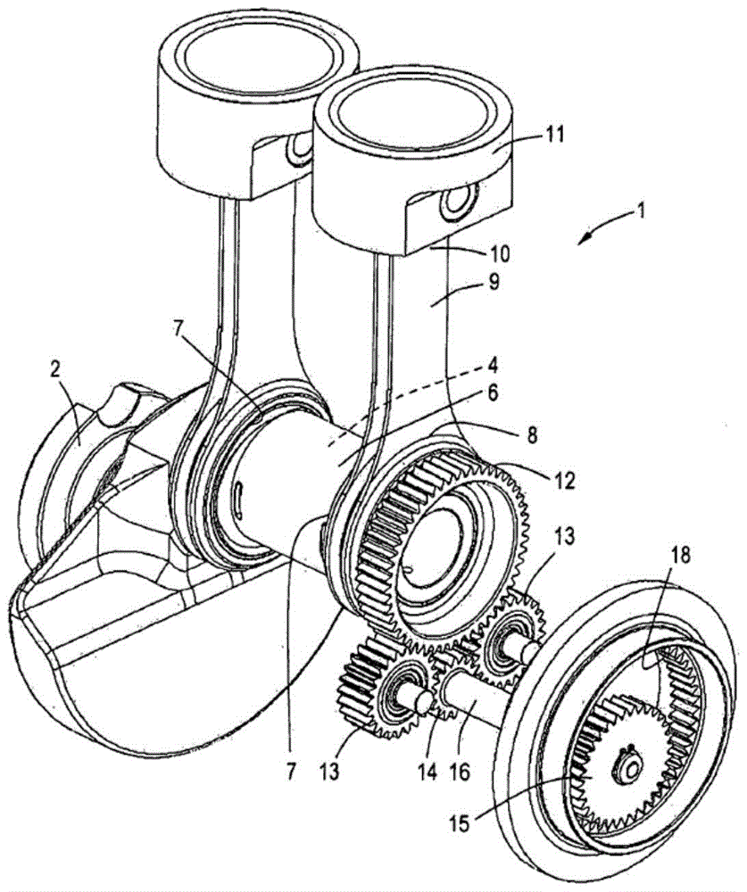
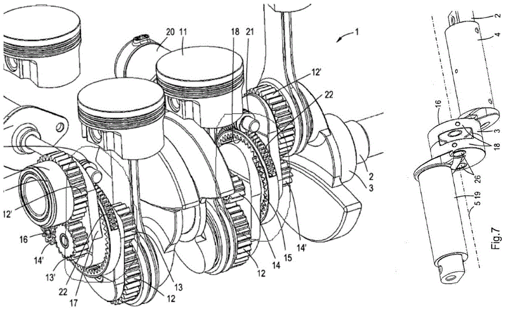
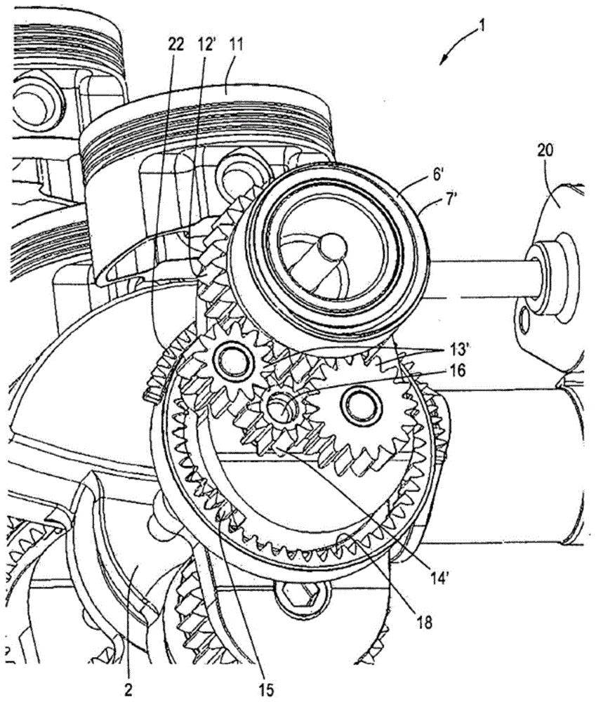
[0003] Although the piston internal combustion engine reported in the 200980123449.4 patent still uses the planetary gear mechanism used in CN1176678A to adjust the speed ratio and use the eccentric crank pin to control the compression ratio, it overcomes the above-mentioned huge mechanism, heavy driving burden, and serious wear and tear. Disadvantages, its obvious advantage is that the half-speed rotation of the crankpin eccentric bearing is controlled by the gear ratio, which is beneficial to reduce friction and improve engine performance, but its most obvious disadvantage is the compression ratio adjustment part, or occupies the crankshaft main shaft that bears heavy load The center of the neck or other moving parts are partially occupied, which not only deteriorates the integrity of the crankshaft, but also greatly reduces the stiffness and strength of the crankshaft; or destroys the overall structure of the crankshaft by using the elongated shaft passing through the center of the crankshaft. Setting the transmission at the center of the crankshaft greatly limits the degree of overlap between the main journal of the crankshaft and the crank pin (hereinafter referred to as the degree of overlap of the crank), which is the basis for the design of a crankshaft with high strength, high stiffness and large crank degree of overlap required for the development of modern engines to high power density. Contradictory requirements
As a result, the latter, with a complex mechanism and a control method suspended outside the machine, on the one hand, directly leads to a great reduction in the overlap of the crank, and also needs to install a thin transmission shaft in the center of the crankshaft, which reduces the strength and stiffness of the crankshaft and the torsional stiffness of the transmission parts. On the other hand, it will inevitably lead to the cumulative load of the multi-cylinder machine being added to the small gear at the control end, making it too strong and the possibility of fatigue damage increased, because the control gear that cooperates with it has to be made very large The diameter of the central internal gear is enlarged, and the control shaft with a large load passes through the center of the crankshaft, which weakens the strength and rigidity of the crankshaft, and also causes difficulties in the design and arrangement of lubricating oil passages and others.
The former mechanism is too complex (such as figure 2 and image 3 ) and directly lead to the overall destruction of the crankshaft, which greatly weakens the strength and rigidity of the crankshaft
It is particularly important to set the control mechanism for driving the eccentric sleeve gear on the heavy-duty main journal. On the one hand, the use of too many gears makes the mechanism complex and the reliability in actual use is reduced. Engines with crank overlap cannot be used, and modern engines are developing in the direction of high power density and large crank overlap

Method used


Image

  • Compression ratio adjustable engine suitable for arbitrary crank overlap without destroying the crankshaft structure
  • Compression ratio adjustable engine suitable for arbitrary crank overlap without destroying the crankshaft structure
  • Compression ratio adjustable engine suitable for arbitrary crank overlap without destroying the crankshaft structure

Examples


Embodiment Construction

[0044] The adjustable compression ratio engine suitable for any crank overlapping degree without destroying the crankshaft structure of the present invention will be described in detail below with reference to the embodiments and accompanying drawings.

[0045] Such as Figure 4 , Figure 5 , Figure 6 , Figure 9 As shown, the non-destructive crankshaft structure of the present invention is suitable for an adjustable compression ratio engine with any degree of crank overlap, including at least one first cylinder 2, and the reciprocating piston 1 located in the first cylinder 2 runs through the first cylinder 2 And the upper end of the connecting rod 3 in the first cylinder 2 is hinged by the piston pin 32, and the other end of the connecting rod 3 stretches out from the lower side of the first cylinder 2 and is hinged to the drive mechanism positioned below the first cylinder 2, the drive mechanism It includes a crankshaft composed of the main journal 24, the first crank a...


PUM


Abstract

An engine with adjustable compression ratio that does not destroy the crankshaft structure and is suitable for any degree of crank overlap has at least one cylinder. When the engine has only one cylinder, on two or one first crank arms of the cylinder, the plane width of the first crank arm Two first ear-shaped protrusions are arranged symmetrically on the center line of the center line, and a through hole is formed on the two or one first ear-shaped protrusion. One end of a pin shaft is fixedly connected to the first auxiliary gear close to the inner surface of the first crank arm, and the other end is fixedly connected to the second auxiliary gear close to the outer surface of the first crank arm. The first auxiliary gear is connected to the first eccentric sleeve gear. meshing, the second auxiliary gear meshes with the sun gear, and when the controlled unit fixedly connected with the sun gear is a worm gear, the controlled unit meshes with the worm drive member rotatably arranged on the cylinder block and is driven by the worm drive unit. The invention can improve the power performance of the engine, reduce fuel consumption, reduce emission pollution and increase the overall rigidity.

Description

technical field [0001] The invention relates to an engine with adjustable compression ratio. In particular, it relates to an engine with adjustable compression ratio that does not destroy the crankshaft structure and is suitable for any degree of crank overlap. Background technique [0002] The traditional reciprocating piston internal combustion engine is limited by the structure of the crank connecting rod mechanism, and the compression ratio cannot be adjusted, which limits the improvement of its performance. As a known technology, many scholars have adjusted the eccentric crank pin through the gear mechanism in many patents as early as 1929 so as to change the compression ratio and improve the performance of the engine. However, many technologies utilize planetary gear mechanisms to adjust the compression ratio, but this is not practical because the crank structure is destroyed. Along with technical progress, the piston type internal combustion engine as reported in CN...

Claims


Application Information

Patent Timeline
Patent Type & Authority Patents(China)
IPC IPC(8): F02B75/04F02D15/04
CPCF02B75/048
Inventor 林建生
Owner TIANJIN UNIV
Learn More