High pressure and low pressure bypass system

A technology of bypass system and high-pressure bypass, which is applied to steam engine devices, machines/engines, mechanical equipment, etc., and can solve problems such as increased cost, short service life, and uncompact structure

Active Publication Date: 2014-07-16
SHANGHAI PINGAN HIGH PRESSURE REGULATING VALVE FACTORY
View PDF4 Cites 23 Cited by
  • Summary
  • Abstract
  • Description
  • Claims
  • Application Information

AI Technical Summary

Problems solved by technology

At present, there are a small number of domestic enterprises producing this bypass system, and due to the difference in system layout and materials used, the performance of the device varies greatly. The main problems are: system device Y-shaped flow channel layout structure, energy-saving series and inclination Unreasonable, it is very easy to cause cavitation and leakage due to partial vaporization of the steam, and the layout of the induction tube is unreasonable, and its length needs to be more than 3 meters. The impedance to noise transmission is small, and it can provide an attenuation of less than 10 decibels.
Therefore, the noise is relatively large during operation, which affects environmental protection. At the same time, due to the uncompact structural layout, waste materials, increase costs, and have defects such as short service life and waste of energy.

Method used


Image

  • High pressure and low pressure bypass system

Examples


Embodiment Construction

[0024] In order to make the technical means, creative features, goals and effects achieved by the present invention easy to understand, the present invention will be further described below in conjunction with specific illustrations.

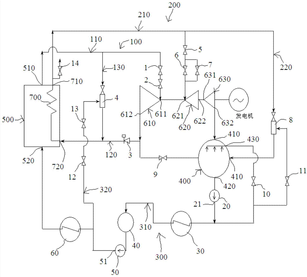
[0025] see figure 1 The high and low pressure bypass system shown includes a high pressure bypass system 100 , a low pressure bypass system 200 , a circulation pipeline 300 and a condenser 400 . The high-pressure bypass system 100 includes a superheating pipeline 110, a reheating pipeline 120, and a high-pressure bypass pipeline 130. The two ends of the superheating pipeline 110 are respectively connected to the steam output end 510 of the boiler 500 and the steam inlet end 611 of the high-pressure cylinder 610. A high-pressure main steam valve 1 and a high-pressure regulating valve 2 are sequentially arranged on the superheating pipeline 110 along the steam advancing direction. The two ends of the heat recovery pipeline 120 are respectively co...


PUM


Abstract

The invention discloses a high pressure and low pressure bypass system. The high pressure and low pressure bypass system comprises a high pressure bypass system connected with a high pressure cylinder, a low pressure bypass system connected with an intermediate pressure cylinder and a low pressure cylinder, a circulation pipeline and a condenser. The high pressure bypass system comprises an overheating pipeline, a backheating pipeline and a high pressure bypass pipeline. The low pressure bypass system comprises a reheating pipeline and a reheating condensation pipeline. The circulation pipeline comprises a circulating water pipeline and a high pressure temperature reducing pipeline. The high pressure and low pressure bypass system has the advantages that the structure is reasonable, the service life is long, unit load adaptability is improved, and a unit can be suitable for frequent start and stop and rapid load rise and fall; under the working condition that a turbine is started or load shedding is conducted, the temperature and the pressure of live steam are reduced through the bypass system, and then the live steam is fed into a reheater, dry burning of the reheater is avoided, and therefore the reheater is protected; in the sudden shedding of part of or all of loads of the unit, a bypass is quickly opened, a working medium is recycled to the condenser, running stability of a boiler is changed, and motion of a safety valve is reduced and even avoided.

Description

technical field [0001] The invention relates to the technical field of steam turbine temperature reduction and pressure reduction, in particular to a high and low pressure bypass system. Background technique [0002] The high-pressure bypass system is arranged on the steam turbine steam recirculation pipeline, which can reduce the high-level steam pressure and temperature to the low-level pressure and temperature adjustment and control through the temperature and pressure reduction device. [0003] The high and low pressure bypass system operates under the combination of cold state, vapor state, hot state and high and medium pressure cylinders. It is easily damaged by high temperature and high pressure difference erosion and vaporization for a long time. At present, there are a small number of domestic enterprises producing this bypass system, and due to the difference in system layout and materials used, the performance of the device varies greatly. The main problems are: s...

Claims


Application Information

Patent Timeline
Patent Type & Authority Applications(China)
IPC IPC(8): F01K11/04
Inventor 陆耀威李飞燕朱峰
Owner SHANGHAI PINGAN HIGH PRESSURE REGULATING VALVE FACTORY
Why Eureka
Try Eureka