
Network cable socket

A network cable socket and network cable technology, which is applied in the direction of the bendable lead wire device, etc., can solve the problems of small contact area between the clamping part and the network cable, the insulation of the network cable is broken, and the network cable is not displayed, so as to ensure stability and increase Clamping area, effect of improving clamping stability

Inactive Publication Date: 2014-07-09
ZHEJIANG OCEAN UNIV
View PDF1 Cites 4 Cited by
  • Summary
  • Abstract
  • Description
  • Claims
  • Application Information

AI Technical Summary

Problems solved by technology

[0002] As introduced in the previous patent (Patent No.: 201320266451.0), the traditional network cable socket mainly relies on clamping parts to press the network cable to restrict the positioning of the network cable. This clamping structure has the following defects: firstly, the clamping The contact area between the holder and the network cable is small, and it is easy to deform the network cable, especially for the circular network cable. Secondly, the position of the network cable in the hole is not displayed, and it will shake left and right with the use of the outside world. It will cause the clamping part to not overwhelm the network cable when it is pressed down, or only press part of the network cable, so that the outer insulation of the network cable will be broken.

Method used


Image

  • Network cable socket
  • Network cable socket
  • Network cable socket

Examples


Embodiment Construction

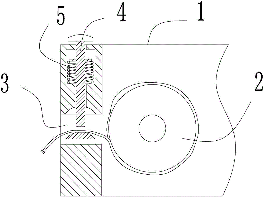
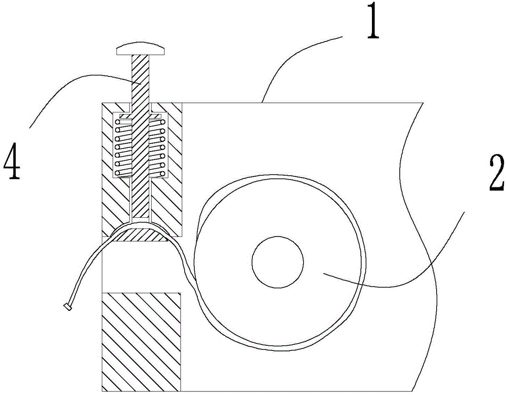
[0014] Such as figure 1 image 3 As shown, a network cable socket includes a shell 1 fixed on the cavity wall, a network cable output hole 3 opened on the shell 1, a rotating shaft is arranged inside the shell 1, and a reel 2 is connected to the reel 2 on the rotating shaft through a disc spring, and the reel 2 is rolled up. A certain length of network cable is wound, and the network cable protrudes through the network cable output hole 3, and a clamping rod 4 for limiting the movement of the network cable is installed on the shell 1 at the network cable output hole 3.

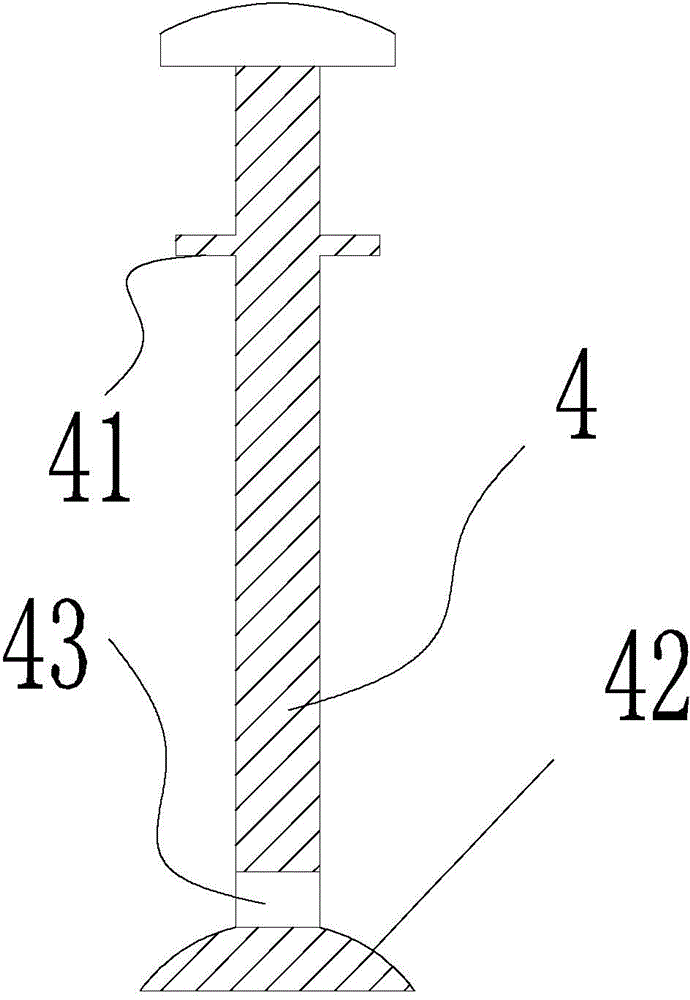
[0015] The connection structure between the clamping rod 4 and the housing 1 is that a rod hole through which the clamping rod 4 passes is formed on the housing 1 above the network cable output hole 3, and a spring chamber is formed in the middle of the rod hole, and a return compression spring is arranged in the spring chamber. The clamping rod 4 passes through the return compression spring, and a baffle pla...


PUM


Abstract

The invention discloses a network cable socket. The network cable socket comprises a shell fixed to a cavity wall, and a network cable output hole formed in the shell, wherein a rotating shaft is arranged in the shell, a coiling shaft is connected to the rotating shaft through a disk-type spring, a certain length of network cable is coiled on the coiling shaft, the network cable stretches out through the network cable output hole, and a clamping rod for limiting movement of the network cable is installed in the position, of the network cable output hole, of the shell. Under the action of a reset spring, the network cable can be clamped in a cavity along with a chuck when being static, the clamping area is increased, and the network cable can be effectively protected and prevented from being clamped to damage.

Description

technical field [0001] The invention relates to a network cable socket. Background technique [0002] As introduced in the previous patent (Patent No.: 201320266451.0), the traditional network cable socket mainly relies on clamping parts to press the network cable to restrict the positioning of the network cable. This clamping structure has the following defects: first, the clip The contact area between the holder and the network cable is small, and it is easy to deform the network cable, especially for the circular network cable. Secondly, the position of the network cable in the hole is not displayed, and it will shake left and right with the use of the outside world. It will cause the clamping part to not overwhelm the network cable when it is pressed down, or only press to part of the network cable, thereby breaking the outer insulation skin of the network cable. Contents of the invention [0003] The invention provides a network cable socket, so that the network cabl...

Claims


Application Information

Patent Timeline
Patent Type & Authority Applications(China)
IPC IPC(8): H01R13/72
Inventor 顾沈明胡超谭小球
Owner ZHEJIANG OCEAN UNIV
Learn More