
Locking component

A component and locking technology, applied in the direction of mechanical equipment, fixtures, etc., can solve the problems of manual operation and low unlocking efficiency

Active Publication Date: 2014-07-09
GREE ELECTRIC APPLIANCES INC
View PDF5 Cites 6 Cited by
  • Summary
  • Abstract
  • Description
  • Claims
  • Application Information

AI Technical Summary

Problems solved by technology

[0004] The purpose of the present invention is to provide a locking assembly to solve the problem of low unlocking efficiency caused by manual unlocking of the locking assembly in the prior art

Method used


Image

  • Locking component
  • Locking component
  • Locking component

Examples


Embodiment Construction

[0021] It should be noted that, in the case of no conflict, the embodiments in the present application and the features in the embodiments can be combined with each other. The present invention will be described in detail below with reference to the accompanying drawings and examples.

[0022] The present invention provides an embodiment of a locking assembly, which is specifically applied to the electrostatic precipitating parts of the air conditioner and the fixing seats at both ends, but the locking assembly of the present invention is not limited to the parts of the air conditioner that need to be snapped or latched. It can also be applied to other structures suitable for this fixing method.

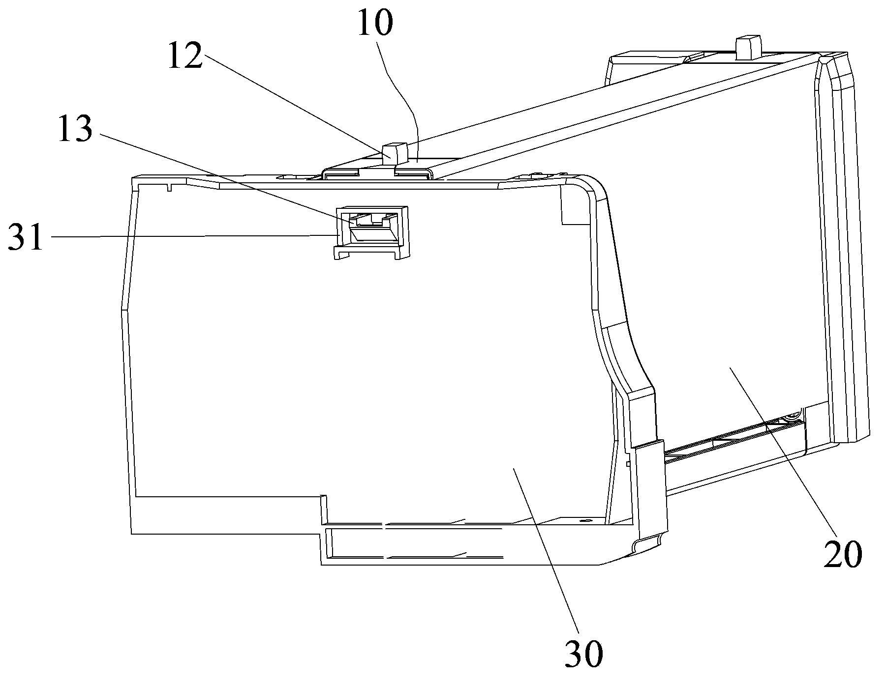
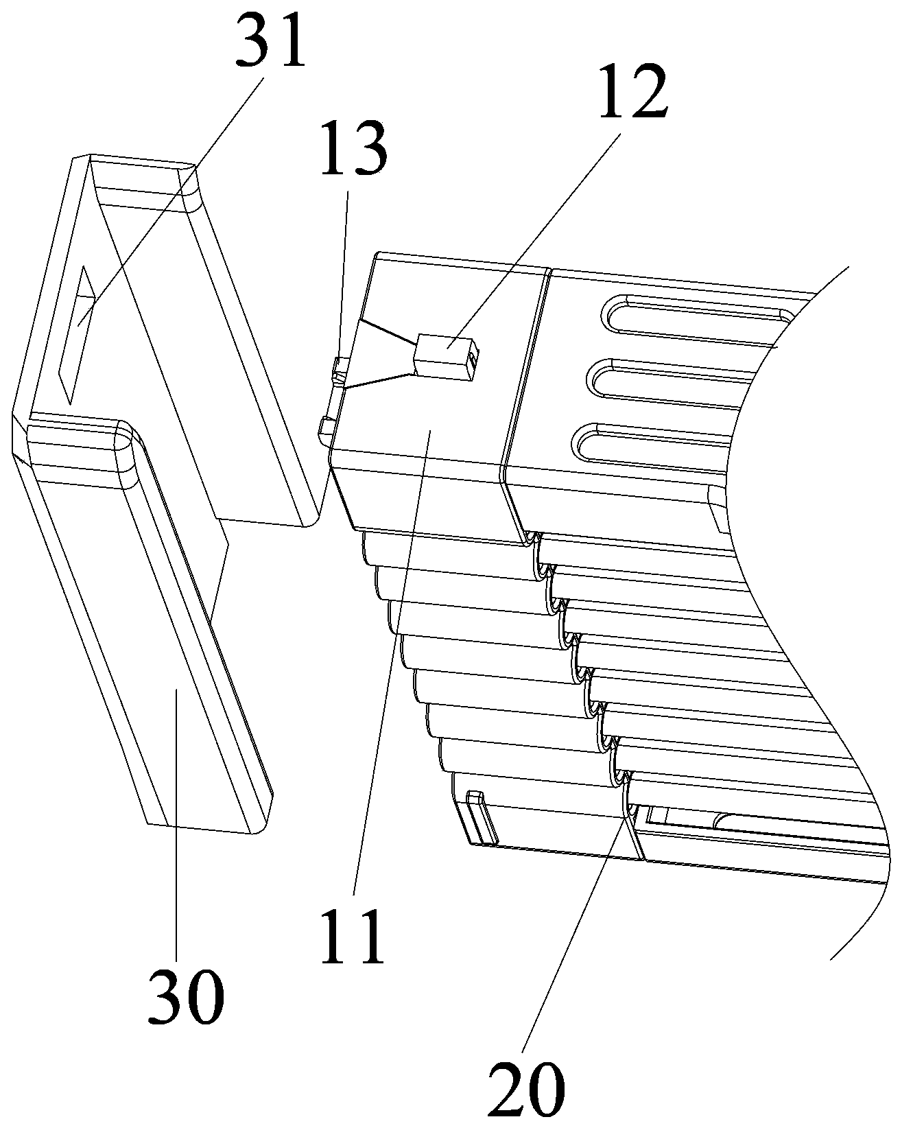
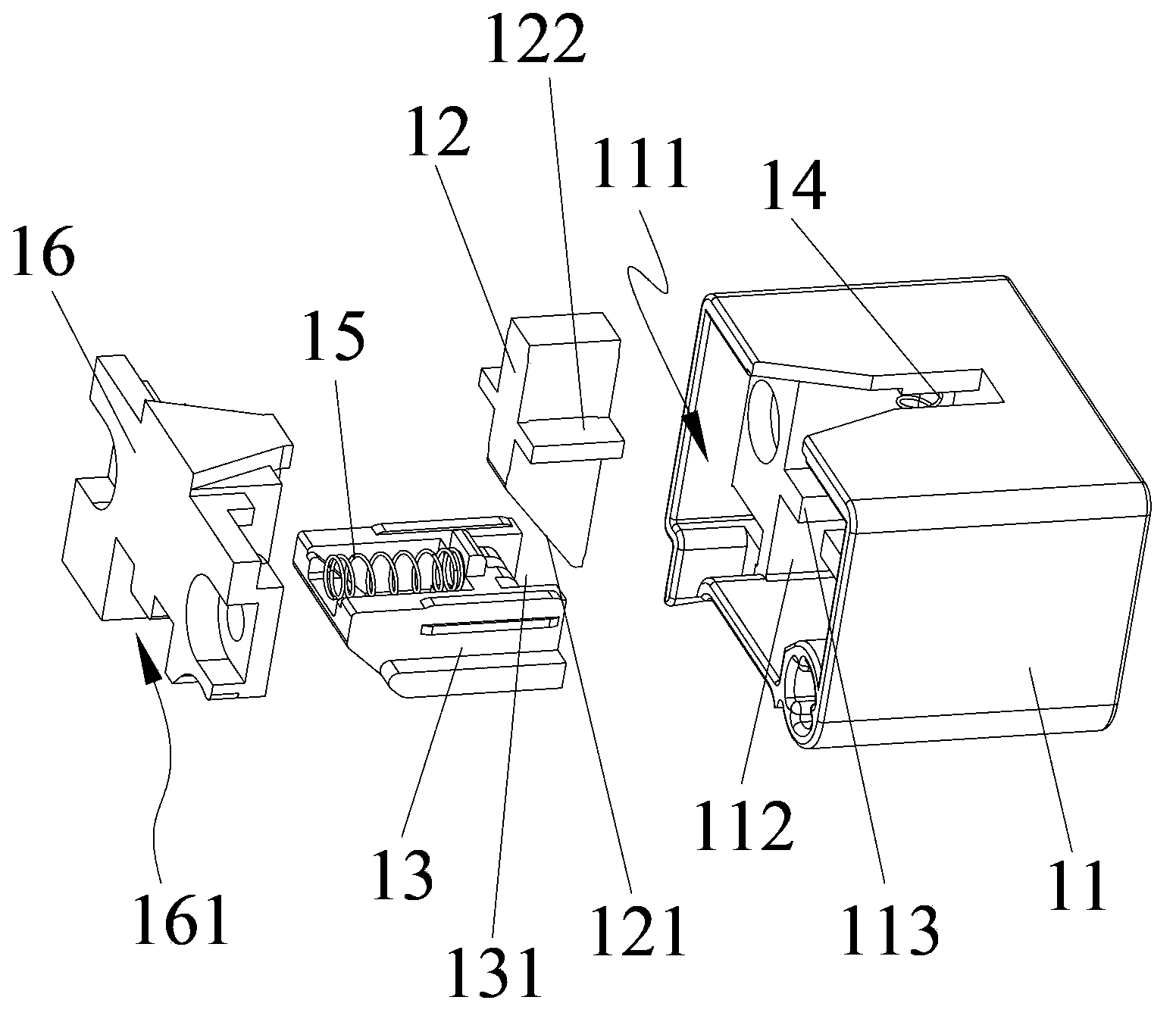
[0023] The locking assembly structure of this embodiment is specifically referred to Figure 1 to Figure 4 , wherein, the two ends of the electrostatic precipitator 20 need to be connected and locked on two fixed seats 30, the locking assembly 10 is detachably mounted on both ends o...


PUM


Abstract

The invention provides a locking component. The locking component comprises a mounting part, a driving part, a driven part, a first elastic part and a second elastic part. The driving part is movably arranged on the mounting part along a first direction and comprises a force application end and a driving end. The driven part is movably arranged on the mounting part along a second direction and comprises a locking end matched with a snapping groove in a part to be fixed and an abutting end in abutting fit with the driving end of the driving part, and the driven part comprises a first position where the locking end is snapped into the snapping groove and a second position where the locking end is away from the part to be fixed. The driving part has a driven part abutting third position and fourth position, the locking end of the driven part abuts against the first position when the driving part is in the third position, and the locking end of the driven part returns to the second position when the driving part is in the fourth position. The first elastic part is connected with the mounting part and the driving part respectively, and the second elastic part is connected with the mounting part and the driven part respectively. By means of the locking component, the problem of low unlocking efficiency caused by the fact that the locking component is needed to be unlocked manually in the prior art is solved.

Description

technical field [0001] The invention relates to a lock assembly. Background technique [0002] In the prior art, the locking methods of two parts through the locking assembly include buckle, latch, magnet attraction and the like. When locked and fixed, it is necessary to press the buckle or push the latch to make the buckle or the latch enter the slot of another object, and fix the two objects together through the limit of the slot; when it is necessary to release the mutual locking, Also provide a push or reverse push to unlock. [0003] The disadvantage of these locking components is that each time the lock is released, it needs to be pressed or pushed manually, especially when there are many buckles and latches, the unlocking efficiency is low. Contents of the invention [0004] The purpose of the present invention is to provide a locking assembly to solve the problem in the prior art that unlocking of the locking assembly needs to be done manually, resulting in low u...

Claims


Application Information

Patent Timeline
Patent Type & Authority Applications(China)
IPC IPC(8): F16B1/04
Inventor 劳承云谢武彬
Owner GREE ELECTRIC APPLIANCES INC
Learn More