
A glass fiber fiberizing machine

A glass fiber and fiberizing machine technology, which is applied in the field of glass fiber fiberizing machine and glass fiber production device, can solve the problems of unstable fiber quality, unstable transmission, large vibration, etc., to ensure stability and reliability. , to ensure stability and consistency, and to improve the effect of production efficiency

Active Publication Date: 2016-01-13
CHANGZHOU JINYUAN MACHINERY EQUIP
View PDF8 Cites 0 Cited by
  • Summary
  • Abstract
  • Description
  • Claims
  • Application Information

AI Technical Summary

Problems solved by technology

[0003] However, the existing glass fiber fiberizing machines have the following defects: firstly, the working surface of the centrifuge and the flame blowing line need to be parallel according to the process requirements, and the current domestic centrifuges cannot guarantee this requirement, the design of the transmission system is unreasonable, and the transmission is not good. Stable, strong vibration, resulting in unstable fiber quality, many changes in fiber distribution, seriously affecting the stability of production; secondly, the concentricity of the centrifugal disc and the burner cannot meet the production needs, and the concentricity of the burner and the cotton cutting cannot meet the technical requirements ;Thirdly, the problem of water leakage in the cold water jacket has always been a big problem for centrifugal glass fiber manufacturers; finally, the centrifuge is a vulnerable part of glass microfiber production, which needs to be replaced frequently, which is time-consuming and laborious

Method used


Image

  • A glass fiber fiberizing machine

Examples


Embodiment Construction

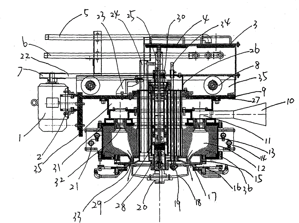
[0012] A glass fiber fibrillating machine, comprising a frame 35, a transmission device, a centrifugal device, a main combustion device and an internal combustion device, the transmission device includes a motor 1 fixed on the motor adjustment frame 2, a motor 1 fixed on the output shaft of the motor 1 Drive pulley 7 and the driven pulley 30 and drive belt 22 that are fixed on the main shaft 25, drive pulley 7 link to each other with the wheel 8 that is fixed on the frame 35, centrifugal device includes main shaft 25, the centrifuge that is fixed on main shaft 25 one ends 18. Supply liquid to the centrifuge 18 and feed the feed pipe 24 of the liquid glass raw material. The feed pipe 24 fixed on the feed pipe fixing frame 23 is connected with the frame 35 and the bottom plate 9. The main combustion device includes a gas supply channel 10, Top plate 31, be arranged on the top plate 31 and several combustion nozzles 32 that are evenly distributed along the circumferential directio...


PUM


Abstract

The invention discloses a glass fiber fibrillating machine. The glass fiber fibrillating machine comprises a rack (35), a transmission device, a centrifugal device, a main combustion device and an internal combustion device, wherein the centrifugal device comprises a main shaft (25), a centrifuge (18) and a feed pipe (24), the transmission device is arranged in a cold water jacket (29), a main shaft (25) which is connected with a cold water jacket (29) through a flange plate (20) is connected with a perpendicularity regulating system (27), the centrifuge (18) is fixedly arranged on the flange plate (20) by threads, and the flange plate (20) is connected with the main shaft (25) as a whole by threads. The glass fiber fibrillating machine has the beneficial effects of being high in fiber forming quality, good in stability, and convenient to install, debug, operate in field and maintain.

Description

technical field [0001] The invention relates to a device for preparing glass fiber in the technical field of machinery, in particular to a glass fiber fibrillating machine. Background technique [0002] At present, the domestic production of glass microfibers all adopts the flame blowing method. The centrifugal blowing method can only produce fibers more than five centimeters. The core equipment of the centrifugal blowing method is the glass fiber centrifugal fiberizing machine. The centrifugal fiberizing machine is a It is a kind of equipment for producing glass fiber from molten liquid glass by means of centrifugal projection. The performance of the centrifugal fiberizer determines the quality and fineness of the produced glass fiber. At present, the domestic centrifugal fiberizing machine is composed of a frame, a transmission device, a centrifugal device, a main combustion device and an internal combustion device. In the production practice of industrial glass fiber pro...

Claims


Application Information

Patent Timeline
Patent Type & Authority Patents(China)
IPC IPC(8): C03B37/04
CPCY02P40/57
Inventor 叶臻泽
Owner CHANGZHOU JINYUAN MACHINERY EQUIP
Learn More