Eureka AIR delivers breakthrough ideas for toughest innovation challenges, trusted by R&D personnel around the world.

Impedance matching system and impedance matching method

A technology of impedance matching and matching modules, which is applied in the direction of discharge tubes, electrical components, plasma, etc., can solve the problems of slow matching speed, insufficient precision, narrow process window, etc., and achieve improved accuracy and speed, fast matching speed, and matching accuracy high effect

Active Publication Date: 2016-12-28
BEIJING NAURA MICROELECTRONICS EQUIP CO LTD
View PDF3 Cites 0 Cited by
  • Summary
  • Abstract
  • Description
  • Claims
  • Application Information

AI Technical Summary

Problems solved by technology

[0003] The existing matcher 2' uses mechanical adjustment to achieve matching, which has the disadvantages of slow matching speed and insufficient precision
There are also some frequency sweeping power supplies to achieve matching by adjusting the frequency, but because the variable frequency range of the sweeping frequency source is relatively narrow, its process window is relatively narrow
Moreover, it cannot complete the matching independently and needs to cooperate with the fixed matcher 2' to achieve matching. In different process windows, the fixed matcher 2' needs to be replaced, so it is only suitable for fixed processes
It is more troublesome to implement under the multi-process window

Method used


Image

  • Impedance matching system and impedance matching method
  • Impedance matching system and impedance matching method
  • Impedance matching system and impedance matching method

Examples


Embodiment Construction

[0047] Embodiments of the present invention are described in detail below, examples of which are shown in the drawings, wherein the same or similar reference numerals designate the same or similar elements or elements having the same or similar functions throughout. The embodiments described below by referring to the figures are exemplary and are intended to explain the present invention and should not be construed as limiting the present invention.

[0048] In describing the present invention, it should be understood that the terms "center", "longitudinal", "transverse", "length", "width", "thickness", "upper", "lower", "front", " The orientations or positional relationships indicated by "rear", "left", "right", "vertical", "horizontal", "top", "bottom", "inner", "clockwise", "counterclockwise" are based on the attached The orientation or positional relationship shown in the figure is only for the convenience of describing the present invention and simplifying the description...


PUM


Abstract

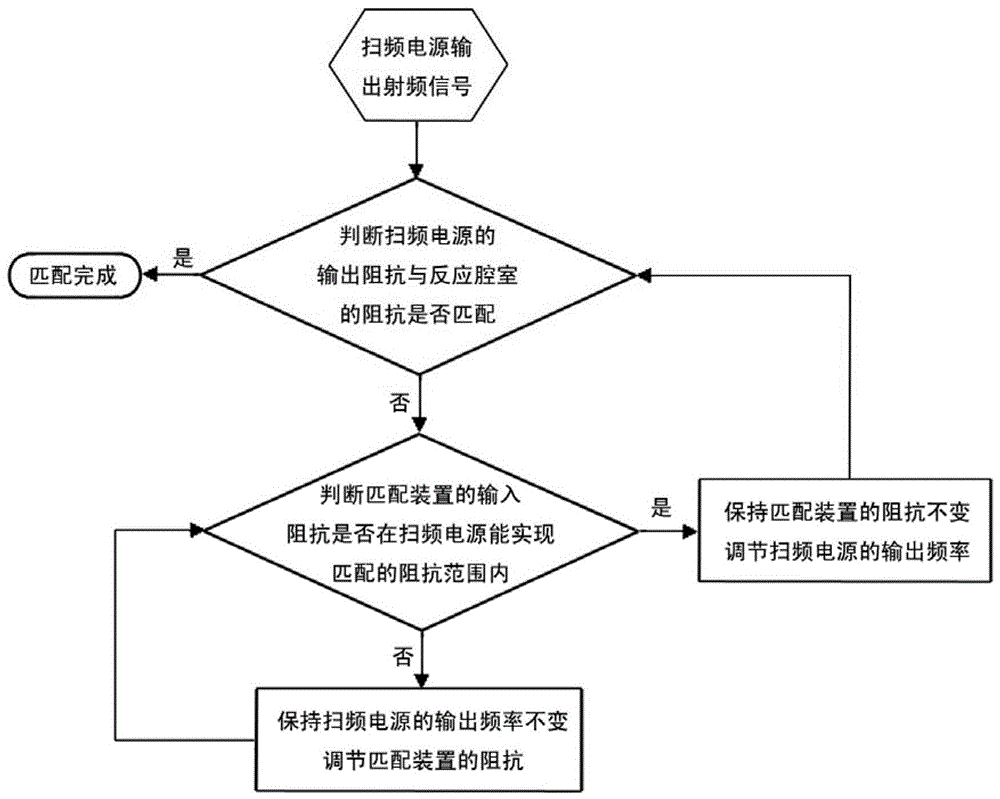
The invention discloses an impedance matching system and an impedance matching method. The system comprises a sweep frequency power supply, a matching device, a sensor, and a controller respectively connected with the sweep frequency power supply, the sensor and the matching device. The controller judges whether the output impedance of the sweep frequency power supply matches the impedance of a reaction chamber. When the output impedance of the sweep frequency power supply mismatches the impedance of the reaction chamber, the controller judges whether the input impedance of the matching device is within the range of impedance which can be matched by the sweep frequency power supply. The controller keeps the impedance of the matching device unchanged and adjusts the output frequency of the sweep frequency power supply to enable the output impedance of the sweep frequency power supply to match the impedance of the reaction chamber if the input impedance of the matching device is within the range of impedance which can be matched by the sweep frequency power supply, or the controller keeps the output frequency of the sweep frequency power supply unchanged and adjusts the impedance of the matching device to enable the input impedance of the matching device to be within the range of impedance which can be matched by the sweep frequency power supply, and then adjusts the output frequency of the sweep frequency power supply to enable the output impedance of the sweep frequency power supply to match the impedance of the reaction chamber.

Description

technical field [0001] The invention relates to the technical field of semiconductors, in particular to an impedance matching system and an impedance matching method. Background technique [0002] Plasma technology is widely used in the fields of semiconductor, flat panel display, solar energy and industry. How to efficiently and rapidly excite plasma has become the key to plasma technology. RF plasma generation as figure 1 As shown, the RF power supply 1' transmits the RF energy to the reaction chamber 3' through the matching device 2', and the RF energy in the reaction chamber 3' excites gases with a certain pressure, such as helium, argon, etc., into plasma Perform etching, cleaning, coating, etc. However, since the output impedance of the RF power supply 1' is a certain resistance value (generally 50Ω), and the impedance of the reaction chamber 3' is not equal to the output impedance of the RF power supply 1', all the RF power cannot be transmitted to the reaction cha...

Claims


Application Information

Patent Timeline
Patent Type & Authority Patents(China)
IPC IPC(8): H01J37/32H05H1/46
Inventor 师帅涛
Owner BEIJING NAURA MICROELECTRONICS EQUIP CO LTD
Why Eureka
Eureka Blog
Learn More