Eureka AIR delivers breakthrough ideas for toughest innovation challenges, trusted by R&D personnel around the world.

Material picking mechanism of injection molding product feeder

A technology of reclaiming mechanism and injection molding products, applied in the field of reclaiming mechanism of injection molding product feeder, can solve the problems of large device structure, inability to install, complicated gripper unit device, etc. The effect of improving work efficiency

Inactive Publication Date: 2014-07-02
昕迪精密机械(东莞)有限公司
View PDF4 Cites 23 Cited by
  • Summary
  • Abstract
  • Description
  • Claims
  • Application Information

AI Technical Summary

Problems solved by technology

How to use an automated method to automatically and efficiently take out the entire molded injection products that are assembled on the receiving platform in multiple rows and columns and transfer them to the subsequent feeding mechanism. There are many opportunities in the large field of automated equipment transportation. Material devices, but these devices are specially designed to adapt to different working conditions and different products, and have strong working conditions and product pertinence
For example, the patent No. 201220127534.7 discloses a new type of gripper device. This device is mainly used for retrieving materials for boxed products and can be used independently. However, if it is used for retrieving materials for injection molding products in this field, there will be the following problems: 1. The device has a large structure and cannot be installed on the injection molding product feeder; 2. The gripper unit is complicated and cannot be used to grip individual small injection molding products

Method used


Image

  • Material picking mechanism of injection molding product feeder
  • Material picking mechanism of injection molding product feeder
  • Material picking mechanism of injection molding product feeder

Examples


Embodiment Construction

[0034] The present invention will be further described below in conjunction with drawings and embodiments.

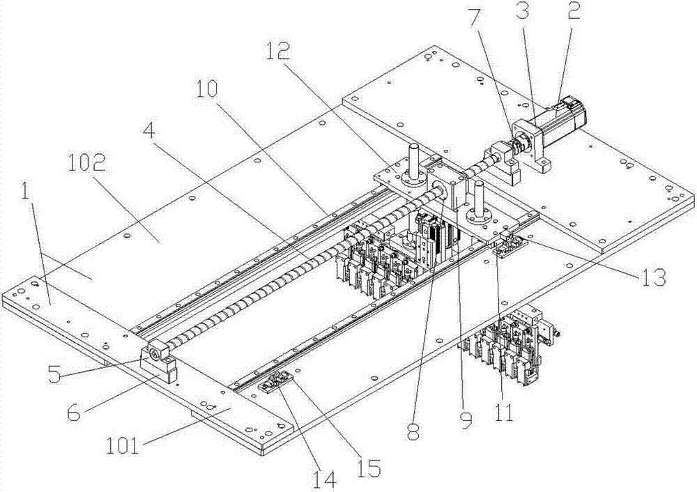
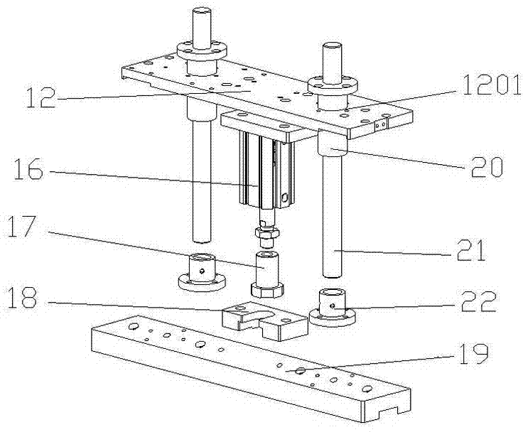
[0035] figure 1 It is an overall three-dimensional structure diagram of Embodiment 1 of the present invention. As shown in the figure, there are four base plates 1, two vertical and two horizontal ones are installed in the shape of a "mouth", and are divided into a vertical base plate 101 and a horizontal base plate 102. The servo motor 2 is installed on one of the longitudinal base plates 101 through the motor fixing seat 3, and the two ends of the screw rod 4 are respectively installed in the screw fixing seat 5, and the screw fixing seat 5 is respectively installed on the two sides through the fixing pad 6. On the vertical base plate 101, one end of the screw rod 4 forms a rotatable connection with the motor shaft of the servo motor 2 through the coupling 7, the screw nut 8 is sleeved on the screw rod 4, and the screw nut 8 is also covered with a wire There are two ...


PUM


Abstract

The invention relates to a material picking mechanism of an injection molding product feeder, and particularly relates to a material picking mechanism of an injection molding product feeder. The material picking mechanism of the injection molding product feeder comprises a translation device, a lifting device and material picking devices, wherein the translation device has a horizontal moving function; the lifting device has an up-down lifting function; the material picking devices have a material picking function; the material picking devices are connected by a plurality of material picking tongs through an adjusting connecting plate to form a group and is installed on a linear guide rail; one ends of the material picking tongs which are combined into a group are positioned, and the other ends of the material picking tongs are dragged by a translation air cylinder to perform contraction and stretching motions; the material picking devices can transfer materials automatically under the drive of the translation device and the lifting device. According to the invention, the problem that injection molding products can not be well linked with a follow-up material dividing mechanism after being completely taken out of a mold and temporally stored on a receiving platform is solved, and the products orderly arranged on the feeder can be automatically and efficiently transferred.

Description

technical field [0001] The invention relates to a material retrieving mechanism of a feeder, in particular to a reclaimer of an injection molding product feeder. Background technique [0002] Injection molding of plastic products generally requires a large number of products to be molded at one time, especially for smaller plastic products, the number of molds at one time is often more. After the injection molding is completed, there needs to be a process of mold release, collection, sorting, and transportation before packaging or other processes. The traditional manual operation method is that the workers directly pick up the injection molding products from the mold, and then collect, organize and transport them. This method is inefficient. Later, there was an automated manipulator, and through its material picking device, the injection molding product could be taken out of the mold at one time and placed on the receiving platform, which greatly improved the work efficienc...

Claims


Application Information

Patent Timeline
IPC IPC(8): B29C45/42
CPCB29C45/1769
Inventor 梁启明
Owner 昕迪精密机械(东莞)有限公司
Why Eureka
Eureka Blog
Learn More