Clutch unit

A clutch, friction clutch technology, applied in the direction of clutch, friction clutch, mechanical drive clutch, etc., can solve unnecessary problems and achieve the effect of less space requirement, reduced loss, and reduced drag torque

Active Publication Date: 2014-06-25
MAGNA POWERTRAIN AG & CO KG
View PDF12 Cites 0 Cited by
  • Summary
  • Abstract
  • Description
  • Claims
  • Application Information

AI Technical Summary

Problems solved by technology

[0007] Of course, in transmissions and drive trains in which such stop functions are not used, additional losses and thus additional heat inputs can also occur due to the flow of cooling oil, since the oil is continuously fed from the oil chamber into the clutch. This oil is accelerated and moved and then churned again in the pool, although cooling may not be necessary in the driving situation involved

Method used


Image

  • Clutch unit
  • Clutch unit
  • Clutch unit

Examples


Embodiment Construction

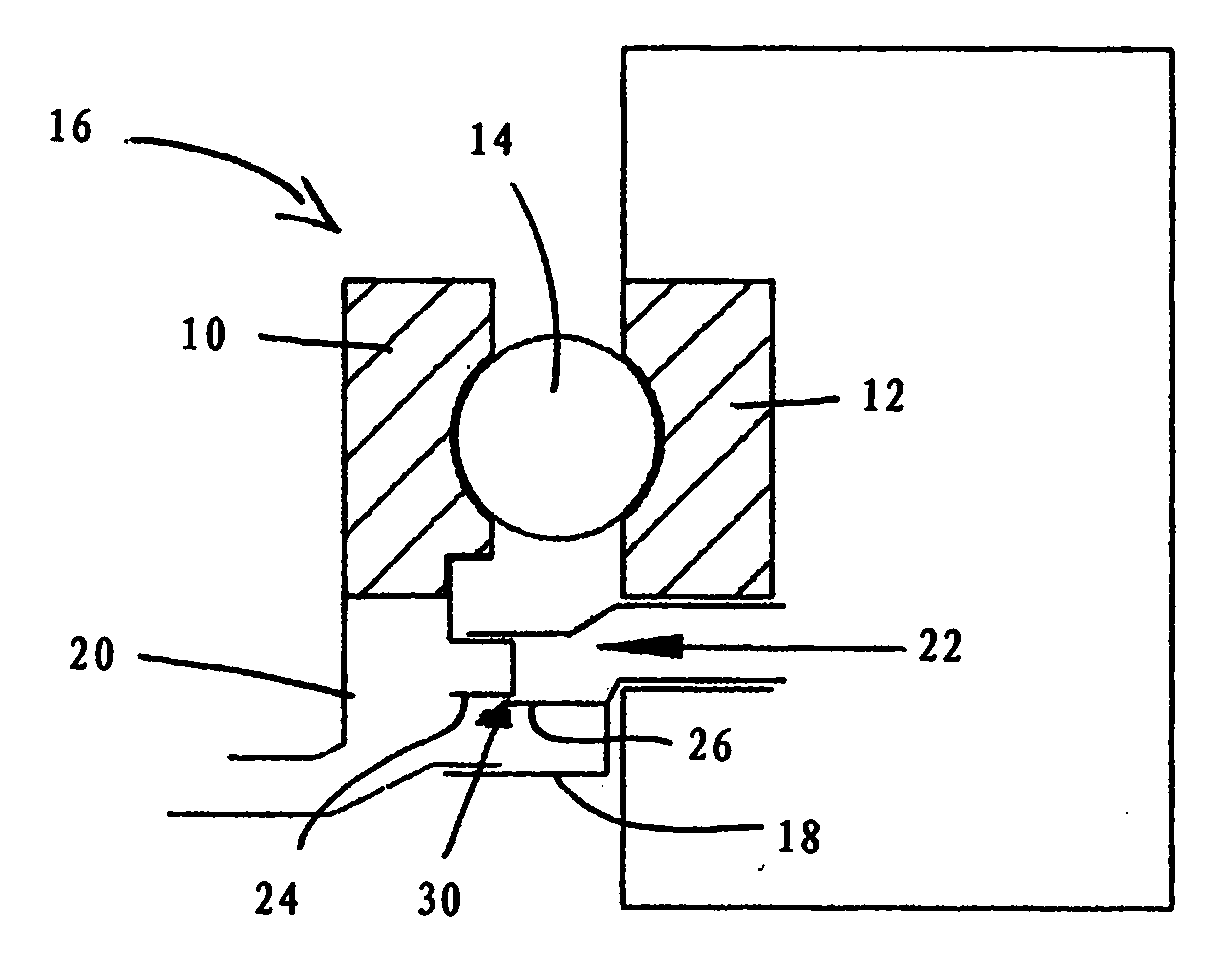
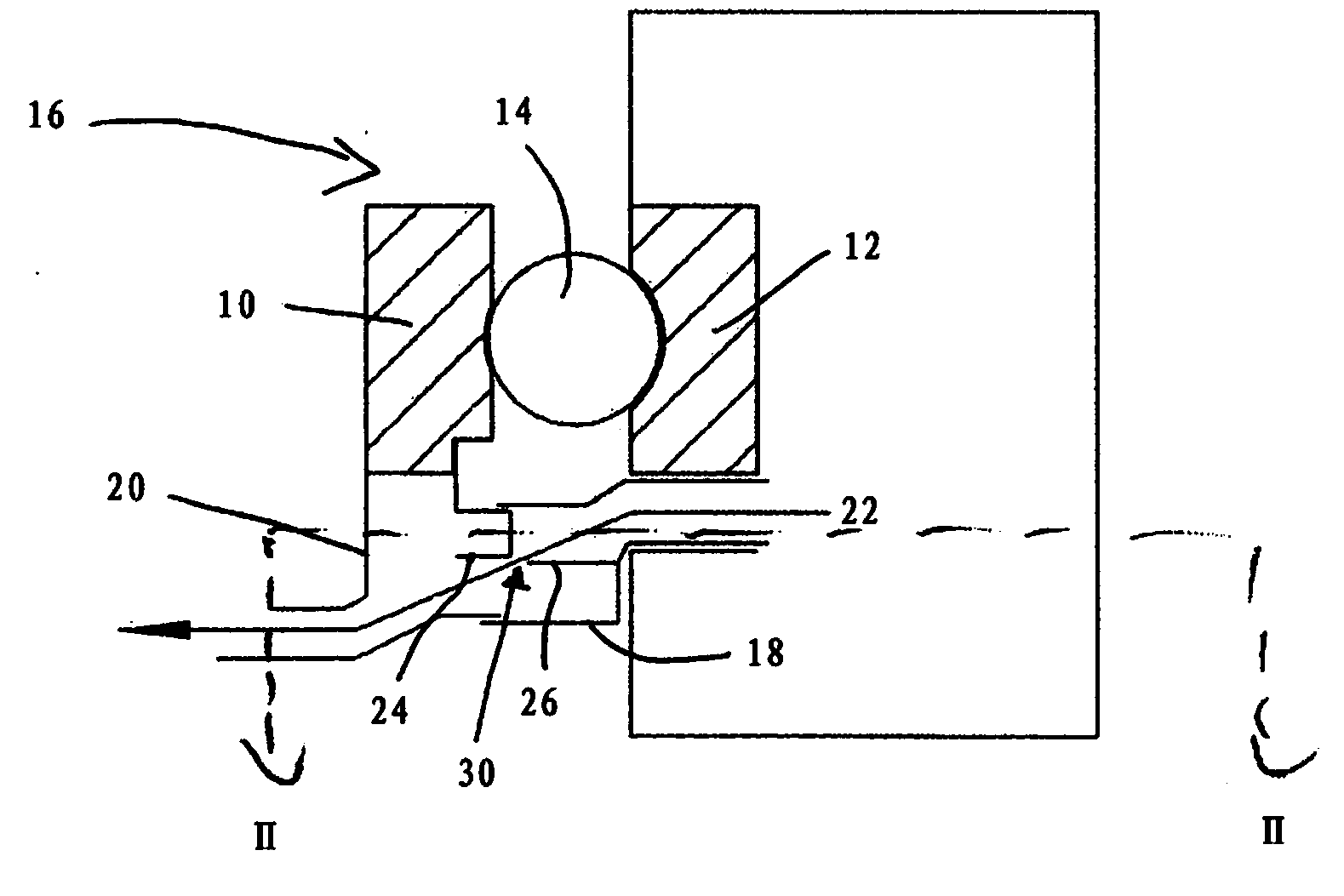
[0031] exist Figure 1a and 1b The clutch unit described in has an integrated metering device for the cooling fluid used for cooling and lubricating the friction clutches of the clutch unit. The friction clutch is not shown here.

[0032] The clutch unit comprises a first ramp ring 10 and a second ramp ring 12 with a plurality of rolling elements 14 interposed therebetween. Together with associated drive means, such as an electric motor, not shown, these elements form an actuator 16 for the friction clutch. The second bevel ring 12 is here stationary (that is to say rotationally fixed and fixed in the axial direction), whereas the first bevel ring 10 is rotatable and axially fixed relative to the second bevel ring 12 . is movable. Alternatively, it is also possible, for example, for the two ramp rings 10 , 12 to rotate in opposite directions, wherein the second ramp ring 12 is supported in the axial direction and the first ramp ring is additionally movable in the axial dire...


PUM


Abstract

The invention relates to a clutch unit for a motor vehicle, comprising a friction clutch and an actuator for actuating the friction clutch, wherein the actuator comprises a first ramp ring and a second ramp ring, at least one of which can be twisted relative to the other ramp ring, in order to exert an axial force on the friction clutch. The clutch unit further comprises a dosing device for the dosed feeding of a cooling fluid to the friction clutch. The dosing device comprises a first dosing section which is associated with the first ramp ring, and a second dosing section which is associated with the second ramp ring, wherein the first dosing section and the second dosing section together delimit a dosing opening for the cooling fluid. The first dosing section and the second dosing section work together in such a manner that the cross section of the dosing opening, which is delimited by the dosing sections, can be changed by a relative twisting of the ramp rings.

Description

technical field [0001] The invention relates to a clutch unit for a motor vehicle, having: a friction clutch; an actuator for actuating the friction clutch, wherein the actuator has a first ramp ring and a second ramp ring, the first ramp At least one of the ring and the second ramped ring is rotatable relative to the other ramped ring to apply an axial force to the friction clutch; and there is a metering device for metering cooling fluid to the friction clutch. Background technique [0002] Clutch units of this type are used in the drive train of motor vehicles for the selective transfer of torque. For this purpose, a friction clutch is provided, which is generally designed as a multidisk clutch and enables a continuously variable transmission of torque. The associated actuator is designed such that it exerts a force axially on the friction clutch. For this purpose, two bevel rings are used which, distributed over the circumference, have a plurality of bevels which are i...

Claims


Application Information

Patent Timeline
IPC IPC(8): F16D13/72F16D23/12
CPCB60K23/08F16D13/72B60K17/344F16D2023/123F16D23/12F16D13/40F16D13/58
Inventor 诺贝特·赫鲁比汉内斯·普克约翰内斯·克亨贝格尔厄恩斯特·里格勒尔
Owner MAGNA POWERTRAIN AG & CO KG
Why Eureka
Try Eureka