
Driving assembly, roller and processing box

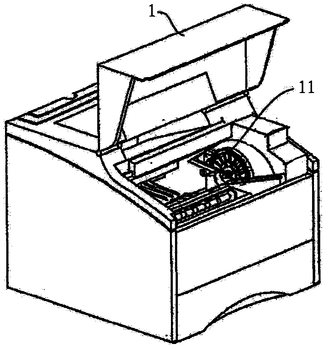
A technology of driving components and driving parts, applied in the field of rollers and process cartridges, can solve problems such as photosensitive drums or developing rollers unable to receive driving force, process cartridges or imaging devices not working normally, drive components and drive shafts stuck, etc., to achieve Reliable performance, reliable fit and connection, and stable work

Active Publication Date: 2014-06-25
PRINT RITE UNICORN IMAGE PROD CO LTD
View PDF13 Cites 13 Cited by
  • Summary
  • Abstract
  • Description
  • Claims
  • Application Information

AI Technical Summary

Problems solved by technology

[0006] However, the above-mentioned drive assembly adopts a drive combination structure of a spherical universal joint. When the process box or imaging device equipped with this drive assembly is transported, this drive assembly is easy to break away from the process box or image forming device, resulting in photosensitive Drum or developing roller cannot receive driving force, resulting in malfunction
[0007] Moreover, since the above-mentioned drive assembly swings randomly in a non-stressed state, when installing or dismounting the drive shaft, it is easy to cause the drive assembly and the drive shaft to be locked together, and even cause the drive assembly and the drive shaft to be locked. damage that prevents the process cartridge or imaging unit from functioning properly

Method used


Image

  • Driving assembly, roller and processing box
  • Driving assembly, roller and processing box
  • Driving assembly, roller and processing box

Examples


no. 1 example

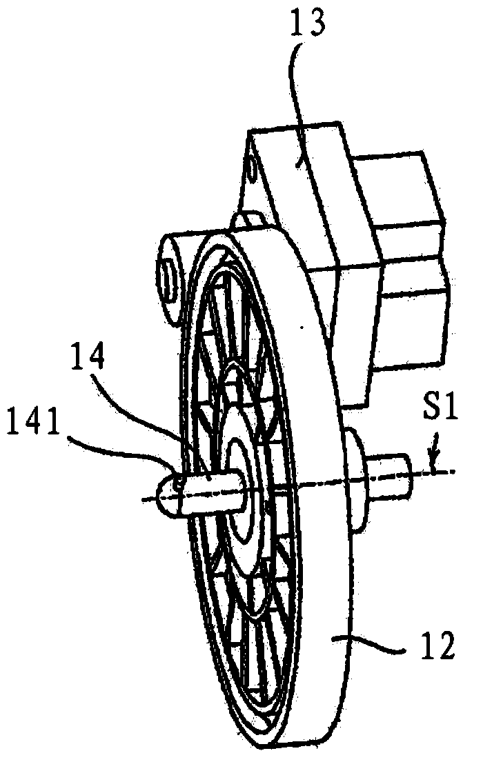
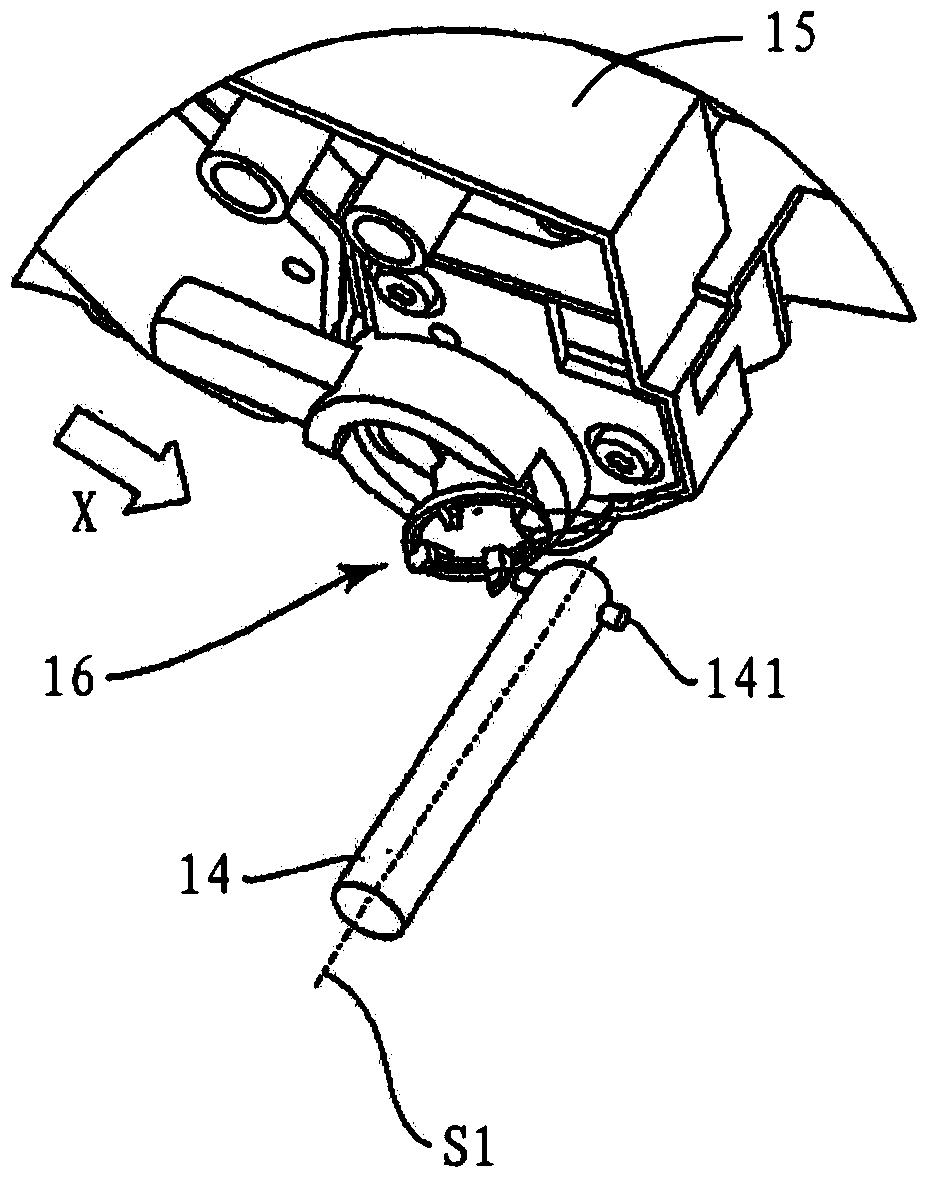
[0049] refer to Figure 4 , Figure 5 and Figure 6 , the driving assembly 2 includes a gear seat 21, a connecting piece 5, a driving wheel receiving piece 3 and a positioning assembly. The driving assembly 2 is installed on the end of the photosensitive drum, developing roller, powder feeding roller, etc., and receives the rotational driving force transmitted from the imaging device such as a printer or copier through the driving wheel receiving part 3, and then transmits the rotating driving force through the connecting part 5 The force thus drives the gear seat 21 to rotate. The housing of the gear seat 21 is formed with an accommodating chamber 26 concaved inward along the axial direction of the gear seat 21. The accommodating chamber 26 is a cylindrical cavity with a bottom, and an opening 24 is provided at one end of the accommodating chamber 26. On the gear seat 21 A fixed end 23 is provided on the other end of the outer wall relative to the opening 24 , and a gear 2...

no. 2 example

[0063] refer to Figure 18 and Figure 19 , on the basis of the first embodiment of the drive assembly, the positioning piece 4 in the first embodiment is designed as Figure 18 The shown positioning sheet 6, the positioning sheet 6 includes a first half sheet 61 and a second half sheet 62, the first half sheet 61 and the second half sheet 62 are respectively provided with a half through hole, the first half sheet 61 and the second half sheet 62 A through hole 63 is formed when mated with each other. When the positioning piece 6 is installed in the positioning groove of the drive assembly, the through hole 63 fits on the rod body and makes the central axis of the driving force receiver parallel to the central axis of the gear seat. The main purpose of the present invention can also be achieved by the positioning piece 6 . Compared with the positioning piece 4 of the first embodiment, the positioning piece 6 of this embodiment lacks the boss 45 of the positioning piece 4, be...

no. 3 example

[0065] On the basis of the first embodiment of the driving assembly, a pin shaft 74 and a spring 77 can also be arranged in the accommodation cavity 76 of the gear seat 71 . refer to Figure 20 and Figure 21 , the axial length of the pin shaft 74 is set to be less than or equal to the diameter of the housing cavity 76, and a through hole 721 is opened at the position where the rod body 72 is located in the housing cavity 76, and the pin shaft 74 passes through the through hole 721, so that the driving force The receiving part can slide along the pin shaft 74 and the pin shaft 74 can move in the receiving cavity 76 along the axial direction of the receiving cavity 76 . The spring 77 is installed in the accommodating cavity 76 , one end of which abuts against the bottom surface 761 of the accommodating cavity 76 , and the other end abuts against the pin shaft 74 . When the driving force receiving part is connected with the driving wheel, the driving force receiving part will ...


PUM


Abstract

The invention provides a driving assembly, a roller and a processing box. The driving assembly comprises a gear seat, a connection piece and a driving force receiving piece, wherein a containing cavity which is concave inwards is formed on the gear seat along the axial direction; the connection piece is mounted in the containing cavity; the driving force receiving piece comprises an inner end part, an outer end part and a rod body part connected between the inner end part and the outer end part; the driving part is connected with the inner end part; the inner end part drives the driving part to rotate around the axis of the connection part; the containing cavity comprises a driven power receiving part arranged at the bottom of the containing cavity and a limiting groove formed in one end part of the containing cavity; the driven power receiving part is connected with a driven part; the driven power receiving part is driven to rotate around the axis of the gear seat by the driven part; the driving assembly further comprises a positioning assembly mounted in the limiting groove; the driving assembly further comprises a positioning assembly mounted in the limiting groove and a rod body part penetrates through the positioning assembly and can do reciprocating sliding relative to the positioning assembly. The invention provides the roller and the processing box which are provided with the driving assembly. The driving assembly, the roller and the processing box have the advantages of being reliable in performance, stable in falling, stable to work and the like.

Description

technical field [0001] The invention relates to the field of printing consumables, in particular to a driving assembly, a roller and a process box constructed by using the driving assembly. Background technique [0002] A process cartridge is usually used in an image forming device as a toner supply source for image forming, and most existing process cartridges can be detachably installed in the image forming device for use. [0003] Usually, many rotating working rollers in the process box, such as powder feeding roller, developing roller and photosensitive drum, etc., they are commonly called rollers, and transmit power to each other through a gear system. Currently, the process cartridge has two structures. The first kind of integrated process cartridge as disclosed in U.S. patent document US5815644, the integrated process cartridge has a photosensitive drum, a developing roller, a cleaning device and a charging device, etc.; The one-piece process cartridge includes a d...

Claims


Application Information

Patent Timeline
Patent Type & Authority Applications(China)
IPC IPC(8): G03G15/00G03G21/18G03G15/08
Inventor 谭武刚杨晓锋李争光范文燚
Owner PRINT RITE UNICORN IMAGE PROD CO LTD
Learn More