
Expansion joint

A technology of expansion joints and expansion gaps, which is used in expansion compensation devices for pipelines, thermal insulation, pipes/pipe joints/pipes, etc. Effect

Active Publication Date: 2014-06-25
NANJING KISEN INT ENG
View PDF13 Cites 3 Cited by
  • Summary
  • Abstract
  • Description
  • Claims
  • Application Information

AI Technical Summary

Problems solved by technology

Bellows-type expansion joints cannot be replaced online due to their complex structure

Method used


Image

  • Expansion joint
  • Expansion joint

Examples


Embodiment Construction

[0017] The present invention will be further described below in conjunction with the accompanying drawings.

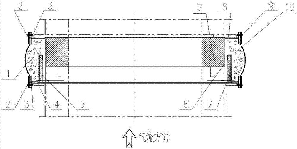
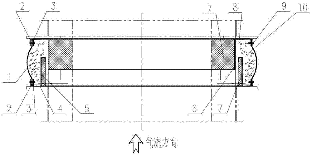
[0018] Such as figure 1 , 2 As shown, the present invention provides an expansion joint, including an expansion deformation piece 1, an outer bead 2, an inner bead 3, an air inlet flange 4, an outer sleeve 5, an inner sleeve 6, a lining 7, and an air outlet flange 8 , Bolts 9, fillers 10, the expansion deformation sheet 1 is connected together with the air inlet flange 4 and the air outlet flange 8 through the bolt 9, the outer bead 2, the inner bead 3. The outer sleeve 5 is connected to the air inlet flange 4, the inner sleeve 6 is connected to the air outlet flange 8, the outer sleeve 5 is wrapped outside the inner sleeve 6, and the outer sleeve 5 and the inner sleeve 6 A gap is left, an expansion gap is left between the end of the outer sleeve 5 and the air outlet flange 8, and an expansion gap is left between the end of the inner sleeve 6 and the air inlet flange...


PUM


Abstract

The invention relates to an expansion joint which comprises an expansion deformation sheet, an air inlet flange, an outer sleeve, an inner sleeve and an air outlet flange. The expansion deformation sheet is connected with the air inlet flange and the air outlet flange. The outer sleeve is connected with the air inlet flange. The inner sleeve is connected with the air outlet flange. The inner sleeve is coated with the outer sleeve. A gap is reserved between the outer sleeve and the inner sleeve. An expansion gap is reserved between the end of the outer sleeve and the air outlet flange. An expansion gap is reserved between the end of the inner sleeve and the air inlet flange. The expansion joint is simple in structure, easy to machine and manufacture, low in production cost and not prone to deformation and damage, so that auxiliary devices additionally arranged in the transportation process are reduced, and the transportation cost is reduced. The simple and effective structural mode of the outer sleeve and the inner sleeve is adopted so as to be used for a metal expansion joint and a non-metal expansion joint.

Description

technical field [0001] The invention relates to an expansion joint, in particular to an expansion joint applied to a calciner system of a preheater in the cement industry. Background technique [0002] The environment of the preheater calciner system in the existing cement industry is harsh, and the temperature of the flue gas at the kiln tail is high, with the highest temperature reaching 1100°C to 1200°C. The dust and flue gas at the kiln tail is corrosive, and the pressure of the calciner system of the preheater at the kiln tail reaches -5500Pa~-8000Pa, so the requirements for the expansion joints used here are relatively high. The expansion joints used here are generally divided into metal expansion joints and non-metallic expansion joints. Because non-metallic expansion joints are cheaper than metal expansion joints, some cement manufacturers use non-metallic expansion joints at the end of the kiln. However, due to the low temperature resistance and short service life ...

Claims


Application Information

Patent Timeline
Patent Type & Authority Applications(China)
IPC IPC(8): F16L51/00C04B7/43
CPCF16L51/04F16L57/04F16L59/21
Inventor 崔恒波李安平高祥召匡祉桦
Owner NANJING KISEN INT ENG
Learn More