
Dyeing vats with pressure accumulator

A technology of dyeing vats and equipment, applied in the field of dyeing vats, can solve problems such as accidents and deformation of dyeing vats, and achieve the effect of ensuring efficiency and quality

Inactive Publication Date: 2015-12-16
CHENGDU ROCK SOLID AUTOMATION TECH
View PDF9 Cites 0 Cited by
  • Summary
  • Abstract
  • Description
  • Claims
  • Application Information

AI Technical Summary

Problems solved by technology

In the dye vat of the horizontal dyeing machine, in order to fully dye the cloth tape, the vat is filled with dye solution and no gaps can be left. However, during the dyeing process, when the temperature rises, the dye solution expands due to heat, but the air without gaps is compressed. When the pressure rises to a certain level, the dyeing vat may be deformed, or even accidents may occur.

Method used


Image

  • Dyeing vats with pressure accumulator
  • Dyeing vats with pressure accumulator
  • Dyeing vats with pressure accumulator

Examples


Embodiment

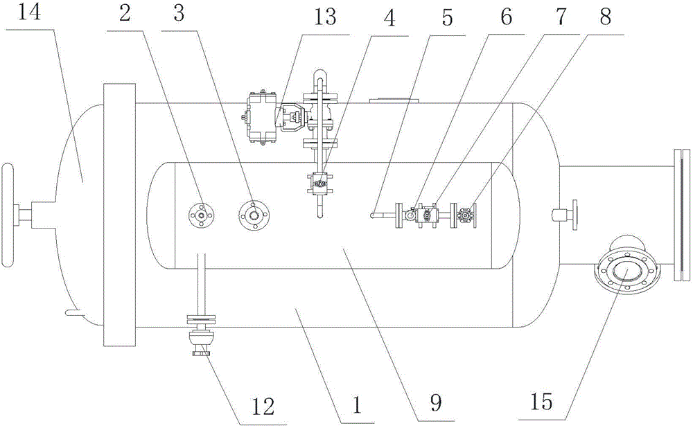
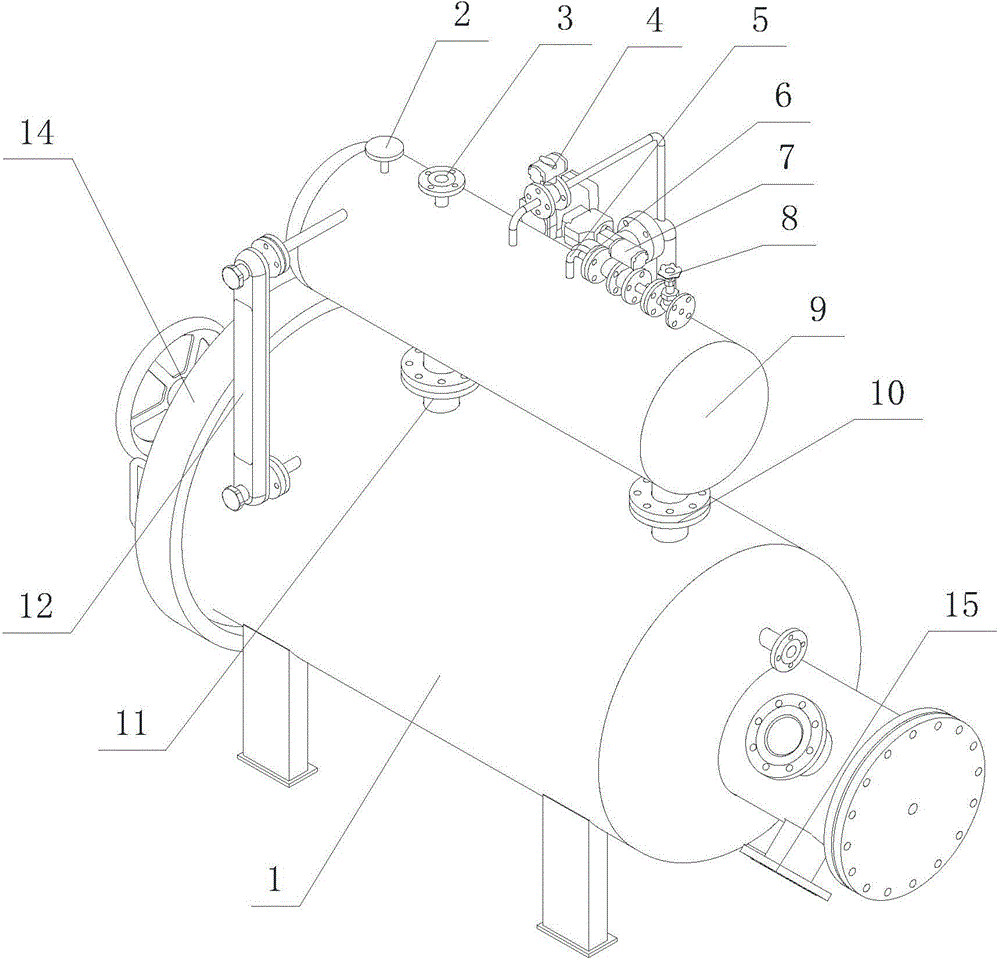
[0015] Example: see figure 1 , figure 2 with image 3 , a dyeing vat with a pressure storage device, comprising a vat 1, the vat 1 is provided with a bobbin inlet and exit door 14 and a dye solution inlet 15, a pressure gauge 2, a safety valve 3 and a degassing valve 4, and an observation dyeing vat The liquid level gauge 12 of the dye liquor height in the cylinder, the cylinder body 1 is provided with a buffer tank 9 communicating with it, the buffer tank 9 is connected with the cylinder body 1 through the exchange channel, and the pressure gauge 2, safety valve 3, off The air valves 4 are all arranged on the buffer tank 9 .

[0016] As preferably, the buffer tank 9 is also provided with a compressed air inlet 5, which is sequentially connected with a check valve 6, a pneumatic ball valve 7 and a stop valve 8; the degassing valve 4 is provided with a suction valve 13.

[0017] Preferably, the buffer tank 9 is a cylinder with spherical ends, and is horizontally arranged a...


PUM


Abstract

The invention provides a dyeing cylinder with pressure accumulation equipment. The dyeing cylinder comprises a cylinder block, a pressure gauge, a safety valve, a deaeration valve and a level gauge. A yarn cone access door is arranged on the cylinder block, dye liquor inlets are formed in the cylinder block, the height of dye liquor in the dyeing cylinder can be observed via the level gauge, a buffer tank which is communicated with the cylinder block is arranged on the cylinder block and is connected with the cylinder block by exchange channels, and the pressure gauge, the safety valve and the deaeration valve are arranged on the buffer tank. The dyeing cylinder has the advantages that the buffer tank is connected onto the cylinder block of the dyeing cylinder, undertakes a task of storing compressed air, is arranged above the cylinder block via the two exchange channels and is integrally filled with the compressed air, the liquor in the cylinder block is expanded when the temperature rises in dyeing procedures, the size of the liquor is increased, accordingly, the air in the buffer tank can be compressed, the air pressure is increased, a certain high-pressure environment can be guaranteed by the compressed air stored in the buffer tank, but deformation damage to the cylinder block due to excessively high pressure can be prevented, and the dyeing efficiency and the dyeing quality can be guaranteed.

Description

technical field [0001] The invention relates to the field of zipper manufacturing, in particular to a dyeing vat with a pressure storage device. Background technique [0002] Dyeing is a very important part of the zipper manufacturing process. The semi-finished cloth tape is wound on the yarn tube, and then the yarn tube is placed in the dyeing vat, and then the dyeing solution is injected into the dyeing vat and circulated. The dye solution in the dyeing vat is heated and pressurized, and the high temperature and high pressure environment can improve the dyeing efficiency and quality. In the dye vat of the horizontal dyeing machine, in order to fully dye the cloth tape, the vat is filled with dye solution and no gaps can be left. However, during the dyeing process, when the temperature rises, the dye solution expands due to heat, but the air without gaps is compressed. If the pressure rises to a certain level, it may cause deformation to the dye vat, or even cause an accid...

Claims


Application Information

Patent Timeline
Patent Type & Authority Patents(China)
IPC IPC(8): D06B23/16
Inventor 胡明华曾国赞蒋进冉浩
Owner CHENGDU ROCK SOLID AUTOMATION TECH
Learn More