A disc ditching machine

A ditching machine and disc technology, applied in the direction of excavation/covering trenches, planting methods, applications, etc., can solve the problems of non-adjustable, large vibration and impact, narrow ditching width, etc., to reduce ditching resistance, The effect of small impact vibration and large ditch width

Inactive Publication Date: 2017-02-15
SOUTHWEST UNIV
View PDF8 Cites 0 Cited by
  • Summary
  • Abstract
  • Description
  • Claims
  • Application Information

AI Technical Summary

Problems solved by technology

[0004] One is to excavate with an excavator: This method of excavating large-scale projects such as sewers, gullies, and canals has good efficiency and high quality, but such machines are not suitable for use in agricultural production;
[0005] The second is to install and drag a small chain on a large tractor: due to the high output speed of the tractor, this method does not match the low speed and high torque of the chain, which can easily cause the chain to break and the efficiency is low;
[0007] (1) The volume and quality of the whole machine are relatively large, so it cannot be used in mountainous and hilly areas; (2) The vibration and impact during ditching work are relatively large, and the bottom of the ditch is prone to unevenness; (3) The width of the ditch is fixed and cannot be adjusted, making it difficult to adapt Various agronomic requirements
[0008] The current research on patents and related literature has some discussions on these issues, but there is no ideal solution.
[0010] The patent application number is "201120179387.3" for "a new type of offset ditching machine", which adopts an offset structure, and also has the problem that the ditch width is too narrow and cannot be adjusted

Method used


Image

  • A disc ditching machine
  • A disc ditching machine
  • A disc ditching machine

Examples


Embodiment Construction

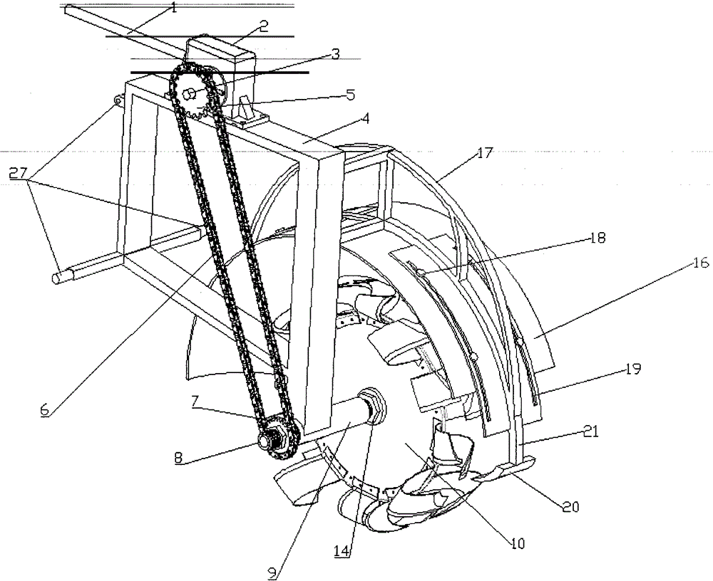
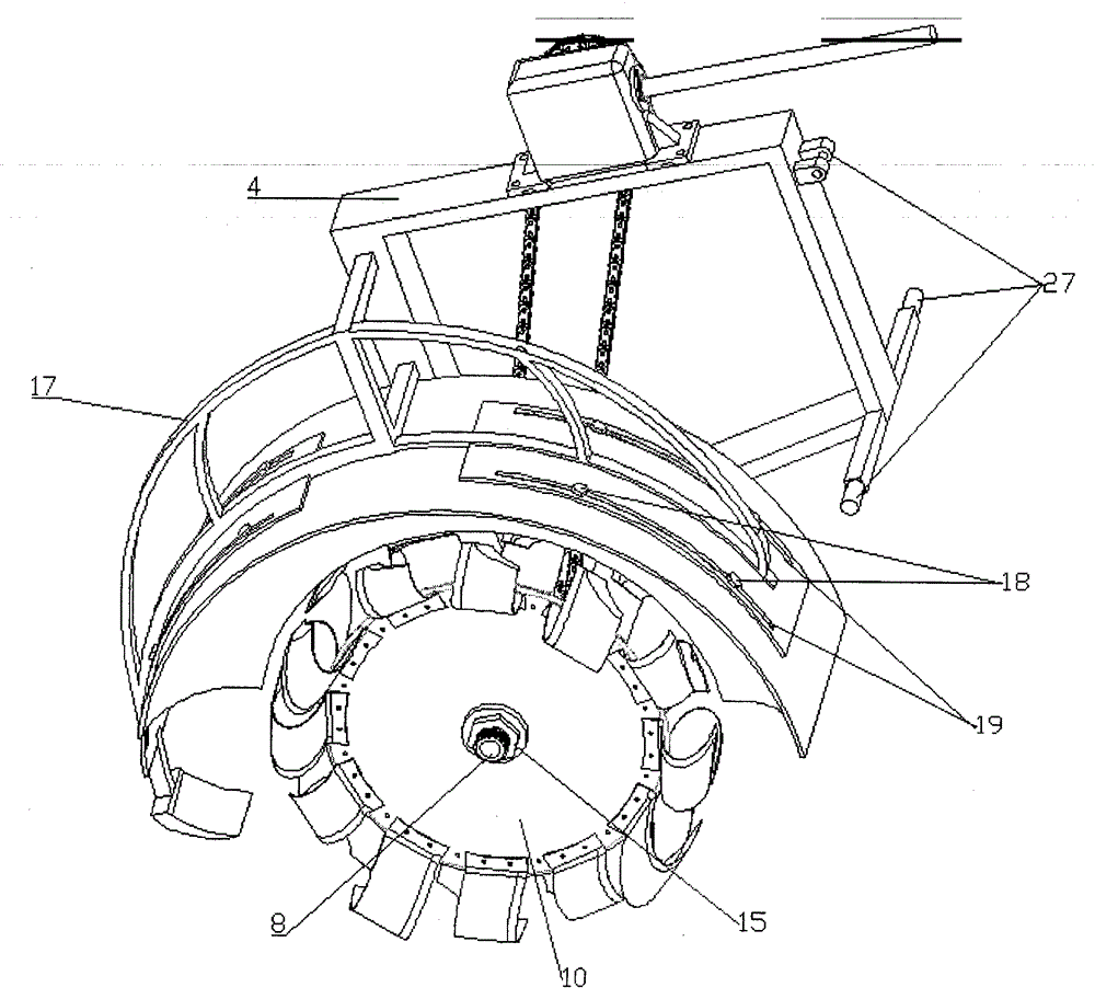
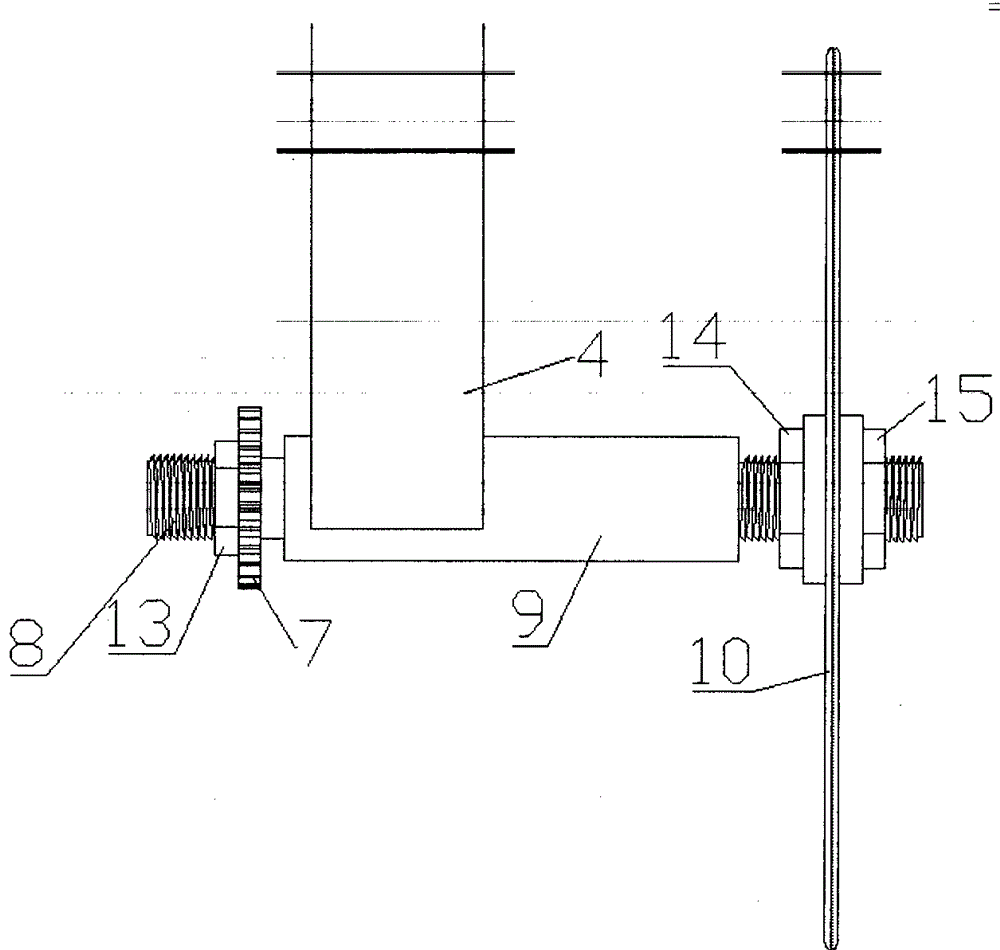
[0034] Such as Figure 1-8 As shown, the power of the tractor is transmitted to the reducer 2 through the input shaft 1 of the reducer, and then transmitted to the driven sprocket 7 by the driving sprocket 5 through the chain 6, and the driven sprocket 7 and the disc shaft 8 are keyed. , the disc shaft 8 and the disc 10 are also keyed, the driven sprocket 7 drives the disc shaft 8 to rotate, and then drives the disc 10 to rotate in the backward direction, and the disc fixed on the disc 10 is opened Knife rotates with disc 10. Width is uniformly distributed on the disc 10 in the form that the law of small ditching knife 24, middle ditching knife 23, large ditching knife 22, small ditching knife 24, middle ditching knife 23, and large ditching knife 22 changes sequentially. The three types of disc ditching knives on the side continuously excavate the soil in front. Due to the adoption of this arrangement that increases in width direction, in the process of ditching, the small t...


PUM


Abstract

The invention discloses a disc ditcher which comprises a frame, a speed reducer, a driving mechanism, a disc ditching component and a soil retaining and scraping mechanism. The disc ditcher is characterized in that the speed reducer is fixed on the upper part of the frame; a three-point type suspension mechanism is arranged on one side of the frame, and the disc ditching component is fixed at the lower end of the other side of the frame and comprises a disc and a ditching knife; the disc is arranged on a disc shaft; an adjusting nut is arranged on the inner side of the disc, and a fastening nut is arranged on the outer side of the disc; an edge at the periphery of the disc is fixed by a bolt, and three types of large, medium-sized and small ditching knives are sequentially and uniformly distributed according to a periodic rule of a small ditching knife-a medium-sized ditching knife-a large ditching knife-a small ditching knife-a medium-sized ditching knife-a large ditching knife; each ditching knife is formed by combining two parts, namely a cutting edge and a main body; the driving mechanism comprises a driving chain wheel, a chain and a driven chain wheel; the driving chain wheel is arranged on an output shaft of the speed reducer; the driven chain wheel is arranged on a disc shaft. The ditcher is simple in structure, light in weight, adjustable in ditching width and slight in shock and impact during ditching operations.

Description

technical field [0001] The invention relates to an agricultural machine, in particular to a disc ditching machine. Background technique [0002] In modern agricultural production, ditching is an important production link. Ditching in the production process is time-consuming and laborious. Therefore, it is very important to design a convenient and practical ditching machine. [0003] Existing mechanized trench excavation techniques are basically divided into three types: [0004] One is to excavate with an excavator: This method of excavating large-scale projects such as sewers, gullies, and canals has good efficiency and high quality, but such machines are not suitable for use in agricultural production; [0005] The second is to install and drag a small chain on a large tractor: due to the high output speed of the tractor, this method does not match the low speed and high torque of the chain, which can easily cause the chain to break and the efficiency is low; [0006] T...

Claims


Application Information

Patent Timeline
Patent Type & Authority Patents(China)
IPC IPC(8): A01C5/06
Inventor 蒋猛李毅蒋光兵邓莹冉嘉梁超何培祥
Owner SOUTHWEST UNIV
Why Eureka
Try Eureka