
Radio-frequency measurement device with variable attenuator

A radio frequency measurement and attenuator technology, applied in transmission monitoring, electrical components, transmission systems, etc., can solve problems such as inability to achieve continuous wideband attenuation, complex control circuits, and insufficient attenuation, and achieve improved low-frequency frequency response and control Simple circuit, improved insertion loss and standing wave effects

Active Publication Date: 2014-06-18
RIGOL
View PDF7 Cites 9 Cited by
  • Summary
  • Abstract
  • Description
  • Claims
  • Application Information

AI Technical Summary

Problems solved by technology

[0006] The embodiment of the present invention provides a radio frequency measurement device with a variable attenuator, which is used to solve the defects that the prior art cannot realize continuous wideband attenuation, and the attenuation is not enough, and the control circuit is complicated

Method used


Image

  • Radio-frequency measurement device with variable attenuator
  • Radio-frequency measurement device with variable attenuator
  • Radio-frequency measurement device with variable attenuator

Examples


Embodiment Construction

[0033] In order to make the object, technical solution and advantages of the present invention clearer, the embodiments of the present invention will be further described in detail below in conjunction with the accompanying drawings. Here, the exemplary embodiments and descriptions of the present invention are used to explain the present invention, but not to limit the present invention.

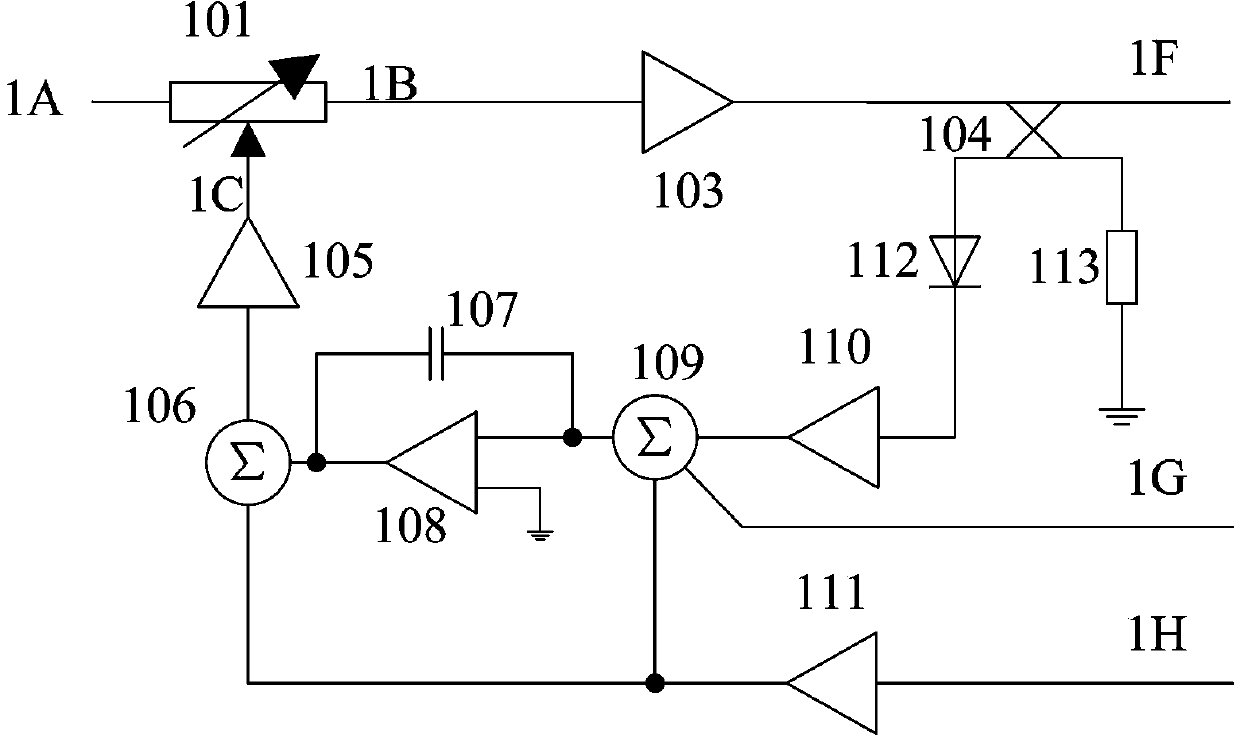
[0034] A radio frequency measurement device with a variable attenuator provided by an embodiment of the present invention, such as figure 1 as shown,

[0035] The measuring device includes: an automatic level control circuit (ALC) with a variable attenuator 101; the output signal 1F of the automatic level control circuit (ALC) controls the variable attenuator to attenuate;

[0036] specific, figure 1 1A is the RF input, and it is output through 1F after passing through the ALC loop. The amplitude of the radio frequency input 1A changes with the change of the input frequency, and the radio...


PUM


Abstract

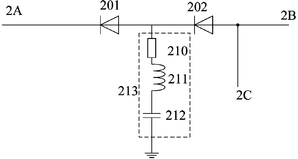
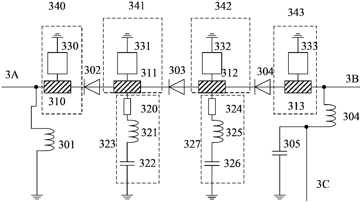
The embodiment of the invention discloses a radio-frequency measurement device with a variable attenuator, wherein the measurement device includes an automatic level control circuit with the variable attenuator. Output signals of the automatic level control circuit control the variable attenuator to perform attenuation. The variable attenuator includes a diode group and a low-frequency matching section. The diode group includes at least two diodes which are serially connected in the same direction. A positive-direction end of the diode group is connected with an output end of the variable attenuator and a negative-direction end of the diode group is connected with an input end of the variable attenuator. One end of the low-frequency matching section is arranged between the two diodes and other end is grounded. The low-frequency matching section is an RLC circuit which includes a resistor, an inductor and a capacitor, which are serially connected. The radio-frequency measurement device with the variable attenuator realizes broadband continuous attenuation so that attenuation amount is increased significantly and the device has a characteristic that the control circuit is significantly simple.

Description

technical field [0001] The invention relates to the field of test and measurement, in particular to a radio frequency measurement device with a variable attenuator. Background technique [0002] In the field of test and measurement, the RF signal source is one of the necessary test and measurement instruments for RF and microwave workers. It can output RF signals of different frequency ranges according to the user's settings. It mainly outputs continuous wave (CW) RF signals. Of course With the development of radar and other technologies, higher requirements are put forward for the radio frequency signal source, and it is also required to be able to output pulse signals. [0003] In the prior art, in order to realize attenuation and modulation, there is an attenuator circuit composed of several switch PIN diodes connected in parallel and several attenuators connected in series. The attenuation of this circuit is large and the response speed is fast. But the disadvantage is ...

Claims


Application Information

Patent Timeline
IPC IPC(8): H04B17/00H04B17/318
Inventor 罗浚洲何毅军王悦王铁军李维森
Owner RIGOL
Learn More