System device for realizing zero power consumption standby of household appliance

A technology for zero-power standby and household appliances, applied in non-electrical signal transmission systems, signal transmission systems, program control in sequence/logic controllers, etc., can solve energy waste, low intelligence, and shorten use Life and other issues, to achieve the effect of remote control distance

Inactive Publication Date: 2014-06-18
朱金荣
View PDF5 Cites 5 Cited by
  • Summary
  • Abstract
  • Description
  • Claims
  • Application Information

AI Technical Summary

Problems solved by technology

At present, most TVs are equipped with set-top boxes, and the TV and the set-top box need to be controlled separately for standby, which is not only troublesome but also consumes a lot of power in standby.
After the household air conditioner is turned off by remote control, if the power plug is not pulled out, the air conditioner is in a standby state all year round, which is not safe and consumes a lot of standby power
Therefore, although this function brings convenience to people, long-term standby of household appliances also causes some problems: first, serious waste of energy consumption; Electromagnetic radiation is still released during standby; the fourth is to accelerate the aging of electrical appliances and shorten the service life
[0004] The above-mentioned schemes have the following disadvantages respectively: 1. The first method adopts manual cutting off of the socket power supply, although it is safe and reliable, but the degree of intelligence is not high
However, when users use it, they need to be equipped with a dedicated wireless remote control, which brings great inconvenience to the use

Method used


Image

  • System device for realizing zero power consumption standby of household appliance
  • System device for realizing zero power consumption standby of household appliance
  • System device for realizing zero power consumption standby of household appliance

Examples


Embodiment Construction

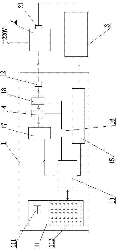
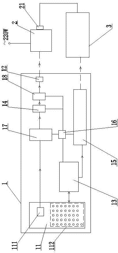
[0027] Such as figure 1 As shown, the present invention includes a remote controller 1 and a wireless smart socket 2 .

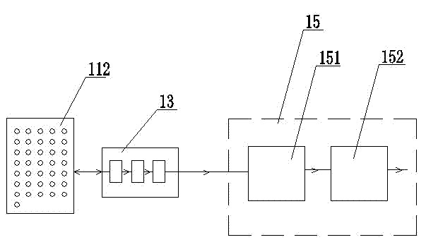
[0028]A keyboard 11 is arranged on the shell of the remote controller 1, and the keyboard 11 is provided with an on key, an off key 111 for radio remote control and a key 112 for infrared remote control. Microprocessor 13, radio signal encoding module 17, signal modulation carrier circuit 14, radio signal amplifying circuit 18, radio signal transmitting antenna 12, infrared signal transmitting circuit 15 are arranged in housing, and for microprocessor 13, radio signal encoding module 17, signal modulation carrier circuit 14, radio signal amplifying circuit 18, infrared signal transmitting circuit 15 provide the battery 16 of power supply, microprocessor 13 is respectively connected with keyboard 11, radio signal encoding module 17, infrared signal transmitting circuit 15, radio signal encoding The output end of the module 17 is connected to the input end of...


PUM


Abstract

A system device for realizing zero power consumption standby of a household appliance particularly relates to the technical field of household appliance remote control, and comprises a remote controller and a wireless intelligent socket, wherein a keyboard is arranged on a shell of the remote controller, a microprocessor, a radio signal coding module, a radio signal transmitting circuit, a radio signal transmitting antenna, an infrared ray signal transmitting circuit and the like are arranged in the shell of the remote controller, and a shell of the wireless intelligent socket is internally provided with a radio receiving module for receiving radio signals, a socket microprocessor, a relay and a driving circuit. Not only can infrared ray signals be transmitted for remotely controlling the household appliance, but also radio signals can be transmitted for remotely controlling the on and off of the wireless intelligent socket. The wireless intelligent socket can receive radio remote control instructions transmitted by the remote controller for intelligently switching on or switching off a power supply of the household appliance, which is plugged on a jack of the wireless intelligent socket through the relay, so that zero power consumption standby of the household appliance can be conveniently realized.

Description

technical field [0001] The invention belongs to the field of intelligent electronic and electrical technology, and in particular relates to the remote control technology of household appliances. Background technique [0002] In recent years, remote control technology has been used more and more widely in household appliances. Many household appliances have remote control standby functions. For example, household appliances such as TVs and air conditioners can be turned off by remote control without disconnecting the power supply. Most TV sets are equipped with set-top boxes at present, and the TV set and the set-top box need to be controlled separately for standby, which is not only troublesome but also consumes a lot of power in standby. After the household air conditioner is turned off by remote control, if the power plug is not pulled out, the air conditioner is in a standby state all year round, which is not safe but also consumes a lot of energy in standby. Therefore, ...

Claims


Application Information

Patent Timeline
Patent Type & Authority Applications(China)
IPC IPC(8): G05B19/04G08C17/02G08C23/04
Inventor 朱金荣朱明宇
Owner 朱金荣
Why Eureka
Try Eureka