
A self-generating railway street light that generates electricity using tension springs and suction

A suction power and self-generating technology, applied in wind power generation, railway signaling, elastic motor, etc., can solve the problems of limited service life and environmental pollution of waste batteries, so as to avoid short service life, avoid power instability, and save power resources. Effect

Inactive Publication Date: 2016-05-18
阜阳知识源互联网科技服务有限公司
View PDF5 Cites 0 Cited by
  • Summary
  • Abstract
  • Description
  • Claims
  • Application Information

AI Technical Summary

Problems solved by technology

[0003] Another disadvantage of existing solar and wind energy street lights is that chemical batteries need to be configured, and chemical batteries require regular maintenance and have a limited service life. Discarded batteries will also pollute the environment, and this situation needs to be improved.

Method used


Image

  • A self-generating railway street light that generates electricity using tension springs and suction
  • A self-generating railway street light that generates electricity using tension springs and suction
  • A self-generating railway street light that generates electricity using tension springs and suction

Examples


Embodiment 1

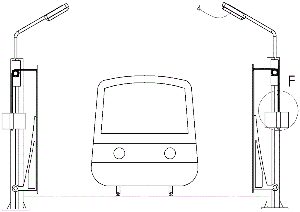
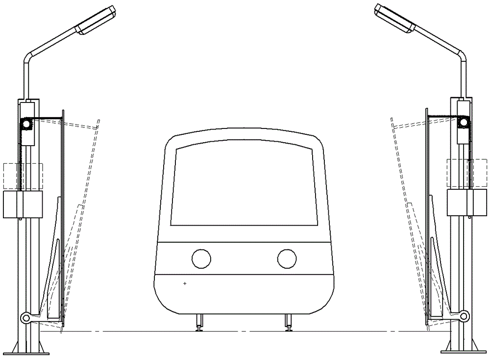
[0040] Embodiment 1, refer to Figure 1 to Figure 4 , the present invention mainly includes a suction swing device, a tension spring elastic potential energy generating device, a time setting device and a street lamp assembly.

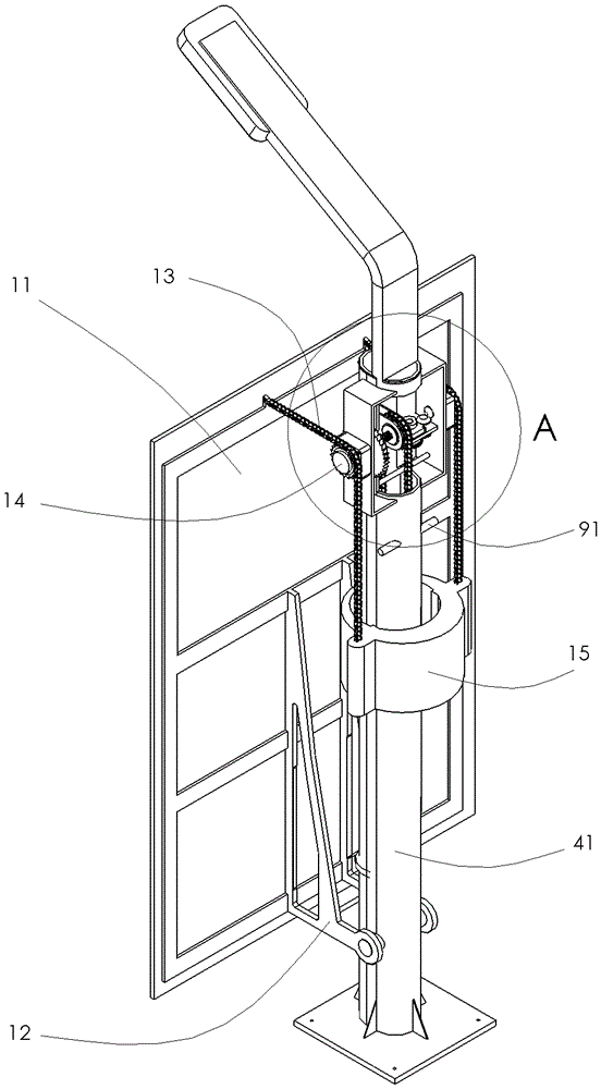
[0041] suction swing device , its main component suction plate 11 is located at the position close to the train and the railway, the suction force produced when each train passes by makes the suction plate 11 swing once towards the direction of the train, and its power will stretch the extension spring 24 from bottom to top , to gradually accumulate elastic potential energy; at the same time, it also provides operating power for the mechanism in the time setting device.

[0042] see image 3 , Figure 4 , the suction swinging device includes a suction plate 11 and a bracket 12 located at the front of the street lamp column 41, two chains 13 on the top of the street lamp column, two sprockets 14, a counterweight 15, a first speed changer 16, a check ...

Embodiment 2

[0062] Example 2: see Figure 13 and Figure 14 The rotation of the sprocket 14 can also be driven by the suction force translation device instead of the suction force swing device, so as to achieve the purpose of generating electricity.

[0063] The components of the suction force translation device are basically the same as the suction force swing device. It includes a suction plate 11 and a bracket 12 arranged at the front of the street lamp column 41, two chains 13 and two chains on the top of the street lamp column. Sprocket 14, balance weight 15, first transmission 16, non-return ratchet mechanism 5, spline shaft 18, top plate 19, compression spring 182 and active conical friction wheel 181, second transmission 39, two support plates 17;

[0064] The difference is: one end of the bracket 12 is fixedly connected with the suction plate 11, the lower part of the bracket 12 is provided with a plurality of rollers 101, and the lower part of the street lamp column 41 is fixed...


PUM


Abstract

The invention relates to a self-generating railway street lamp which utilizes tension spring and suction force to generate power. When passing through, the oscillating device swings with the suction force, and the oscillating force makes the elastic potential energy generating device of the tension spring accumulate elastic potential energy, and the elastic potential energy generating device of the tension spring is regulated by the mechanical time setting device at night, releasing the elastic potential energy to drive the generator to generate electricity , for street lighting. The beneficial effect is that the suction power generated when the high-speed train is running is used to generate electricity, and the electric power for railway street lamp lighting is provided, thereby avoiding the disadvantages of unstable electric power of existing wind energy and solar street lamps. It also saves power resources of the public grid. Using tension springs to store the elastic potential energy of power generation instead of batteries to store electricity, avoids the environmental pollution of chemical batteries, and also avoids the shortcomings of short life and frequent maintenance of chemical batteries.

Description

technical field [0001] The invention belongs to lighting equipment, in particular to a street lamp which utilizes natural energy to generate electricity. Background technique [0002] In order to save energy and protect the environment, there have been street lamps that utilize solar energy and wind energy to provide electricity. These two natural energy street lamps are especially suitable for lighting along railway lines. Because the lighting of long-distance railway lines consumes considerable power resources. However, both energy sources are unstable. For example, in continuous rainy days, the power supply of solar street lights becomes a problem. In continuous windless or light windy weather, wind energy street lights will stop working. It has become an important subject to study a street lamp along the railway that utilizes stable natural energy for power supply. [0003] Another disadvantage of existing solar and wind energy street lights is that chemical batteri...

Claims


Application Information

Patent Timeline
Patent Type & Authority Patents(China)
IPC IPC(8): B61L9/04B61L13/02
CPCF03D9/16F03D5/06F03D9/00F21S8/086F21S9/026F05B2240/9113Y02E60/16Y02B20/72Y02E10/70Y02E10/728F03G1/02F03G7/08Y02E10/72Y02E70/30F21S9/043F03G7/081
Inventor 冯静
Owner 阜阳知识源互联网科技服务有限公司
Learn More