
Automatic car coupler control system and application thereof

An automatic control system and coupler technology, applied in railway car body parts, railway vehicle coupling accessories, railway couplings, etc., can solve the problems of difficult installation, many compressed air pipelines, and high manufacturing costs, and reduce installation. Parts and installation space, assembly and maintenance are simple, and the effect of reducing joints and pipes

Active Publication Date: 2014-06-18
QINGDAO SRI TECH CO LTD
View PDF5 Cites 12 Cited by
  • Summary
  • Abstract
  • Description
  • Claims
  • Application Information

AI Technical Summary

Problems solved by technology

However, the structure of the control system in this patent is quite complicated, with many control units and many and lengthy compressed air pipelines, resulting in more components and high manufacturing costs (about twice as high), and because there are too many pipelines , and there are crossovers, the number of pipeline joints increases, and there are more intermediate links in the connection, which makes assembly and maintenance more difficult, and workers are prone to make mistakes during installation or assembly, so the cost of use is also higher
At the same time, because the technical scheme adopted in this patent has too many pipelines, more space is required for installation, which will not only bring about difficulties in installation, but also inevitably increase the difficulty in designing the coupler.
Especially in this patent, when the left end of the MRP valve fails, when the compressed air leading to the intake end of the two-position three-way valve V4 suddenly disappears, the electric hook will be forcibly retracted, which will cause the interruption of the train circuit and seriously affect the normal operation of the train.

Method used


Image

  • Automatic car coupler control system and application thereof
  • Automatic car coupler control system and application thereof
  • Automatic car coupler control system and application thereof

Examples


Embodiment 1

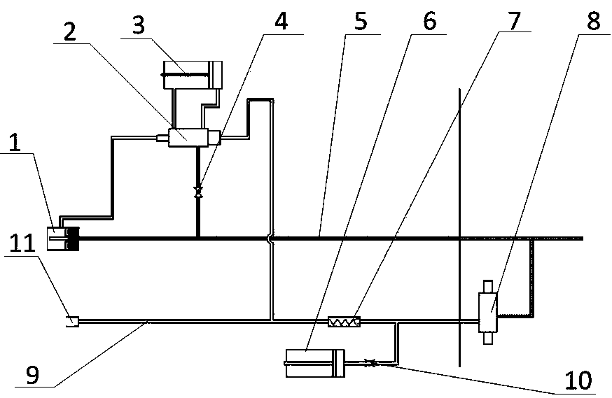
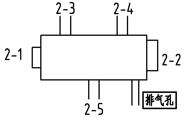
[0051] A kind of coupler automatic control system of the present embodiment, such as figure 1 , figure 2 As shown, the system includes main air pipeline 5, unhook pipeline 9, MRP main air valve 1, UC unhook air valve 11, electric hook push cylinder 3, unhook cylinder 6, air control valve 2, manual stop valve 4. One-way valve 7, throttle valve 10 and manual solenoid valve 8, the air control valve 2 is a two-position five-way valve, such as figure 2 As shown, the two-position five-way valve includes an air-controlled auxiliary control port 2-1, a main control port 2-2 of the air-controlled valve, a first working port 2-3 of the air-controlled valve, and a second port of the air-controlled valve. Working port 2-4, air inlet 2-5 and exhaust hole of the air control valve, the air inlet 2-5 of the air control valve 2 is connected to the manual shut-off valve 4 and then connected to the main air pipeline 5 phases are connected, such as Figure 5a , 5b As shown, the air outlet ...

Embodiment 2

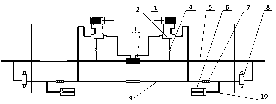
[0053] This embodiment provides the application of the coupler automatic control system in Embodiment 1 when controlling the coupler connection (structure such as image 3 shown), including the following processes:

[0054] Step 1, in the standby state, the main air pipeline 5 supplies compressed air, the MRP valve 1 is closed, there is no compressed air at the left end of the MRP valve 1, and the manual shut-off valve 4 is in a conducting state (such as Figure 5a shown), the compressed air in the main air pipeline 5 enters the air inlet 2-5 of the air control valve 2 through the manual stop valve 4, passes through the first working port 2-3, and then enters the front end of the electric hook push cylinder 3, Keep the electric hook retracted, and the two couplers to be connected contain the same system and are also in the same state. The two systems are connected through the MRP valve 1 and the UC uncoupling air valve;

[0055] Step 2, as the coupler completes the connection...

Embodiment 3

[0059] This embodiment provides the application of the automatic coupler control system of Embodiment 1 when controlling the uncoupling of the coupler (structure such as image 3 shown), including the following processes:

[0060] Step 1, press the manual solenoid valve 8, the compressed air in the main air pipeline 5 enters the uncoupling pipeline 9 through the air inlet and the air outlet of the manual solenoid valve 8;

[0061] Step 2, the compressed air entering the uncoupling pipeline 9 is divided into two paths, one path passes through the throttle valve 10 and enters the uncoupling cylinder 6 to promote mechanical uncoupling, one path passes through the one-way valve 7 and then is divided into two paths, one of which enters the The main control terminal 2-2 of the air control valve 2 controls the reversing of the air control valve 2, and two of them enter the UC unhook air valve 11, and the compressed air fed into the unhook pipeline 9 enters the docking through the UC ...


PUM


Abstract

The invention provides an automatic car coupler control system and the application of the automatic car coupler control system. The automatic car coupler control system comprises a main air pipeline, an uncoupling pipeline, an MRP main air valve, a UC uncoupling air valve, an electric coupler pushing air cylinder, an uncoupling air cylinder, a pneumatic control valve and a manual control electromagnetic valve. An air inlet of the pneumatic control valve is communicated with the main air pipeline. The auxiliary control end of the pneumatic control valve is communicated with the left end of the MRP main air valve. Two work ports of the pneumatic control valve are communicated with a front port and a rear port of the electric coupler pushing air cylinder respectively. The master control end of the pneumatic control valve is communicated with the uncoupling pipeline. The right end of the MRP main air valve is communicated with the main air pipeline. The UC uncoupling air valve is communicated with the uncoupling pipeline. The uncoupling air cylinder is communicated with the uncoupling pipeline. The uncoupling pipeline is communicated with an air outlet of the manual control electromagnetic valve. An air inlet of the manual control electromagnetic valve is communicated with the main air pipeline. According to the automatic car coupler control system and the application of the automatic car coupler control system, a car coupler can be automatically controlled through the simple structure and the assembling difficulty and the maintenance difficulty are reduced.

Description

technical field [0001] The invention belongs to the technical field of coupler connection for rail transit vehicles, and in particular relates to an automatic control system for a subway coupler and its application. Background technique [0002] In rail vehicles, the coupler is used to connect the carriages. If the coupler is uncoupled and connected manually, the workload is huge, the labor is dangerous, and the labor cost is high. Therefore, it needs to be improved to realize automatic control. Specifically, it is required to realize the automatic connection of the mechanical hook and the electric hook when the coupler is connected without manual operation; when the coupler is uncoupled, the decomposition of the electric hook and the mechanical hook can be completed after the driver presses the unhook button. [0003] In the prior art, domestic couplers already have control systems with similar functions. The invention patent with the publication number CN101698412A (couple...

Claims


Application Information

Patent Timeline
IPC IPC(8): B61G7/00
Inventor 杨庆龙吴刚姜晓东张晋伟邓大伟张勇阙红波杜利清
Owner QINGDAO SRI TECH CO LTD
Learn More