How to take out flexible components and how to separate substrates
A separation method and soft technology, applied in the field of semiconductor technology, to overcome the problem of precise alignment of components, improve the back-end process, overcome the low removal rate and difficulty in mass production
- Summary
- Abstract
- Description
- Claims
- Application Information
AI Technical Summary
Problems solved by technology
Method used
Image

Examples
no. 1 example
[0073] Figures 1A to 1F It is a schematic cross-sectional view of a method for taking out a flexible component according to the first embodiment of the present invention.
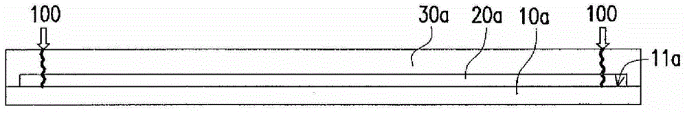
[0074] Please refer to Figure 1A , providing a first carrier 10a. The first release layer 20a and the first flexible substrate 30a are successively formed on the first surface 11a of the first carrier 10a, and all sides of the first release layer 20a and the first flexible substrate 30a have been formed at this moment. First pre-cut 100 . In one embodiment, the first flexible substrate 30a covers the first release layer 20a and the periphery of the first flexible substrate 30a is in contact with the first carrier 10a.
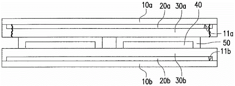
[0075] Please refer to Figure 1B , providing a second carrier 10b, a second release layer 20b, a second flexible substrate 30b and at least one flexible element 40 are sequentially formed on the first surface 11b of the second carrier 10b. In one embodiment, the second flexible substr...
no. 2 example
[0089] Figures 2A to 2G It is a schematic cross-sectional view of a method for taking out a flexible component according to the second embodiment of the present invention.
[0090] Please refer to Figure 2A , providing a first carrier 10c. A first release layer 20c and a first flexible substrate 30c are sequentially formed on the first surface 11c of the first carrier 10c. At this time, the first side (such as Figure 2A The first release layer 20c and the first flexible substrate 30c on the right side in ) have undergone first pre-cutting 200 . In one embodiment, the first flexible substrate 30c covers the first release layer 20c and the periphery of the first flexible substrate 30c is in contact with the first carrier 10c.
[0091] Please refer to Figure 2B , providing a second carrier 10d, a second release layer 20d, a second flexible substrate 30d and at least one flexible element 40 are sequentially formed on the first surface 11d of the second carrier 10d. In one...
no. 3 example
[0105] Figures 3A to 3C It is a schematic cross-sectional view of a method for removing a soft component according to the third embodiment of the present invention. The third embodiment is similar to the first embodiment, except that the second flexible substrate 30b and the second carrier 10b of the first embodiment are separated by the existing method, while the third embodiment The two flexible substrates 30b and the second carrier 10b are separated by the method of the present invention.
[0106] First, do 1A to 1E , then turn the entire set upside down. In particular, in the step of providing the carrier board 10b in the third embodiment, all sides of the second release layer 20b and the second flexible substrate 30b on the second carrier board 10b have been pre-cut for the second time 300 (as Figure 3A shown), but the second pre-cutting step described above is not performed in the first embodiment.
[0107] refer to Figure 3B , a fifth cutting 302 is performed ...
PUM
 Abstract
Description
Claims
Application Information
 - Generate Ideas
- Intellectual Property
- Life Sciences
- Materials
- Tech Scout
- Unparalleled Data Quality
- Higher Quality Content
- 60% Fewer Hallucinations
Browse by: Latest US Patents, China's latest patents, Technical Efficacy Thesaurus, Application Domain, Technology Topic, Popular Technical Reports.
© 2025 PatSnap. All rights reserved.Legal|Privacy policy|Modern Slavery Act Transparency Statement|Sitemap|About US| Contact US: help@patsnap.com