Connection structure between wheel hub and steel wire

A connection structure and steel wire technology, applied in the direction of wheels, spoke wheels, hubs, etc., can solve problems such as easy to break, reduce efficiency, increase difficulty, etc., and achieve the effect of convenient installation

Active Publication Date: 2015-12-30
GIANT KUNSHAN
View PDF7 Cites 0 Cited by
  • Summary
  • Abstract
  • Description
  • Claims
  • Application Information

AI Technical Summary

Problems solved by technology

[0002] A bicycle wheel is composed of a rim, a hub, steel wires fixed on the rim and the hub, and tires on the rim respectively at both ends. At present, the fixing methods of the steel wire and the hub mainly include; one is that the end of the steel wire is bent into a Right angle, also known as J-shaped steel wire, the J-shaped steel wire passes through the corresponding fixing hole on the hub, and is positioned on the hub with the upper end of the steel wire, and the other end of the J-shaped steel wire is fixed on the rim, because the J-shaped steel wire has been severely bent , the J-shaped steel wire connected to one end of the hub is prone to breakage during use (even during installation), especially when riding on bumpy roads; the second is that the steel wire has ends, referred to as straight-pull steel wires. The steel wire has one end and one end is connected to the hub. First, the hub ring is processed into several grooves, and then the straight-pull steel wire has one end and one end is inserted into the corresponding groove, and the straight-pull steel wire is positioned by the end. The other end of the straight-pull steel wire is fixed to the rim. Since the straight-pull steel wire is not bent, the strength of the steel wire is increased. However, the design and processing of the groove on the hub are very demanding. The distribution of the groove must be It must be consistent with the specifications, and the extension direction of the groove must be consistent with the actual force direction at both ends of the straight-pull steel wire, so as to ensure a reliable connection between the steel wire and the hub. Therefore, the actual hub processing increases the difficulty and reduces the efficiency.

Method used


Image

  • Connection structure between wheel hub and steel wire
  • Connection structure between wheel hub and steel wire
  • Connection structure between wheel hub and steel wire

Examples


Embodiment Construction

[0016] One of embodiment:

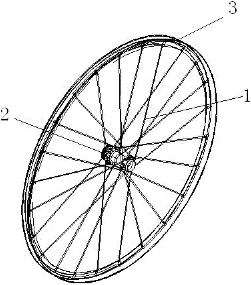
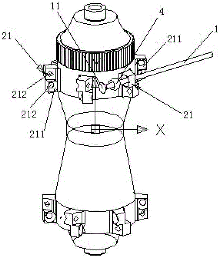
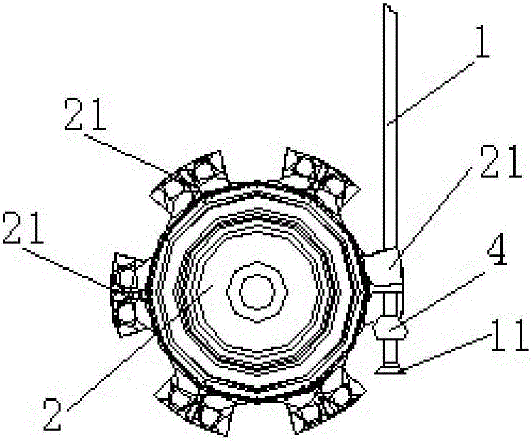
[0017] A connection structure between a wheel hub and steel wires, each steel wire on the wheel is a straight-pull steel wire 1 with an end 11, each of the straight-pull steel wires 1 passes through a spherical washer 4, and passes through After the corresponding connecting convex portion 21 on the hub 2 is fixed on the wheel rim 3, each spherical washer 4 is provided with a through hole for the straight-pull type steel wire to pass through, and each connecting convex portion 21 is provided with The fixing holes are convenient for straight-pull steel wires to move through, and one side of each fixing hole is formed with a spherical concave surface to facilitate the free rotation of the corresponding spherical washer.

[0018] The second embodiment:

[0019] On the basis of one of the examples, such as figure 1 , figure 2 with image 3 As shown, the same side of the hub 2 forms a plurality of connecting protrusions 21 uniformly distributed in th...


PUM


Abstract

The invention discloses a connecting structure for a wheel hub and steel wires. Each steel wire on a wheel is a direct-pull steel wire with a tip; each direct-pull steel wire passes through a stop block, and is fixed to a wheel rim after movably passing through a corresponding connecting bulge on the hub; opposite faces of each stop block and the corresponding connecting bulge respectively form an arc-shaped convex face and an arc-shaped concave face which are convenient for the corresponding direct-pull steel wire to freely rotate; each stop block a spherical washer; a through hole convenient to the corresponding direct-pull steel wire to pass through is formed in each spherical washer; a fixing hole convenient for the corresponding direct-pull steel wire to movably pass through is formed in each connecting bulge; a spherical concave face used as the arc-shaped concave face is formed at one side of each fixing hole. According to the connecting structure disclosed by the invention, the steel wires can be easily installed on the wheel hub, and moreover, the steel wires connected between the wheel hub and the rim are not easy to break off; the connecting structure is very useful and valuable.

Description

technical field [0001] The invention relates to the improvement of the wheel structure, in particular to the connection structure between the steel wire on the wheel and the hub, especially the connection and fixation between the steel wire of the bicycle wheel and the hub. Background technique [0002] A bicycle wheel is composed of a rim, a hub, steel wires fixed on the rim and the hub, and tires on the rim respectively at both ends. At present, the fixing methods of the steel wire and the hub mainly include; one is that the end of the steel wire is bent into a Right angle, also known as J-shaped steel wire, the J-shaped steel wire passes through the corresponding fixing hole on the hub, and is positioned on the hub with the upper end of the steel wire, and the other end of the J-shaped steel wire is fixed on the rim, because the J-shaped steel wire has been severely bent , the J-shaped steel wire connected to one end of the hub is prone to breakage during use (even during...

Claims


Application Information

Patent Timeline
Patent Type & Authority Patents(China)
IPC IPC(8): B60B1/00B60B27/04
Inventor 周铭恩
Owner GIANT KUNSHAN
Why Eureka
Try Eureka