
Gravity steel wire conveyor belt horizontally travels through the degaussing frame device

A conveyor belt, gravity type technology, applied in the field of wire conveyor belt degaussing devices, can solve the problems of conveyor belt tearing, demagnetizer damage and other problems, and achieve the effect of ensuring safe operation.

Active Publication Date: 2016-03-30
BAOSHAN IRON & STEEL CO LTD
View PDF5 Cites 0 Cited by
  • Summary
  • Abstract
  • Description
  • Claims
  • Application Information

AI Technical Summary

Problems solved by technology

[0003] The mechanical structure of the degausser dedicated to various conveyor belts must have: the adjustment function that can automatically return to the center following the conveyor belt, the balance function, the anti-sideways function of the conveyor belt, etc., otherwise the degausser will be destroyed by the friction or impact of the conveyor belt , the conveyor belt will also be torn, resulting in serious consequences

Method used


Image

  • Gravity steel wire conveyor belt horizontally travels through the degaussing frame device
  • Gravity steel wire conveyor belt horizontally travels through the degaussing frame device
  • Gravity steel wire conveyor belt horizontally travels through the degaussing frame device

Examples


Embodiment Construction

[0019] The present invention will be further described below in conjunction with the accompanying drawings and specific embodiments.

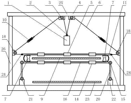
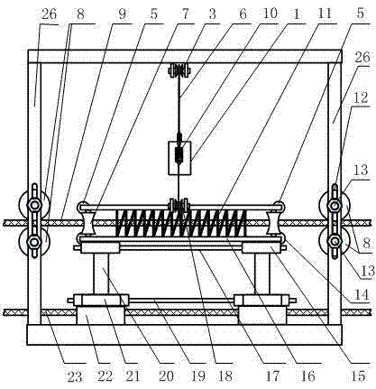
[0020] see figure 1 and figure 2 , a gravity-type steel wire conveyor belt horizontally traverses a degaussing frame device, comprising a degaussing frame frame 25, a steel wire rope 6, a weight 1, a diverting pulley 18, a degaussing coil frame 16, and a rocker mechanism;

[0021] Two upper pulleys 3 are installed side by side on the upper beam 4 of the degaussing frame frame 25, and a diverting pulley 18 is installed on the side beams on both sides of the degaussing frame frame frame 25. One end of the wire rope 6 is connected to the left side of the degaussing coil frame 16 in the degaussing frame frame frame 25. Side connection, that is, degaussing coil frame and wire rope left side connection point 24, the other end passes through diverting pulley 18, upper pulley 3, heavy bell 1, upper pulley 3, diverting pulley 18 and is connected with ...


PUM


Abstract

The invention discloses a gravity type steel wire conveying belt horizontal passing-through demagnetization frame device which comprises a demagnetization frame framework (25), a steel wire rope (6), a counter weight (1), deflecting pulleys (18), a demagnetization coil frame (16) and a rocker arm mechanism. One end of the steel wire rope is connected with the left side edge of the demagnetization coil frame located in the demagnetization frame framework, the other end of the steel wire rope penetrates through one deflecting pulley, one upper pulley (3), the counter weight, another upper pulley and another deflecting pulley in sequence and is connected with the right side edge of the demagnetization coil frame, and the conveying belt passes through a front clamping plain roller (8), enters a demagnetization coil (11) in the demagnetization frame framework and then leaves through a rear clamping plain roller. Waist drum shaped pulleys (7) are mounted on the left side edge part and the right side edge part of the demagnetization coil frame, upper edge pulleys (5) are mounted on the front upper portion and the rear upper portion of the demagnetization coil frame, and lower edge pulleys (14) are mounted on the front lower portion and the rear lower portion of the demagnetization coil frame, and the demagnetization coil is located in the middle of the demagnetization frame framework. The demagnetization coil frame is mounted on the rocker arm mechanism, the rocker arm mechanism can swing left and right by swinging a rocker arm (20), and therefore the demagnetization coil frame can swing left and right.

Description

technical field [0001] The invention relates to a degaussing device for a steel wire conveyor belt, in particular to a gravity-type automatic centering conveyor belt horizontally running degaussing frame device. Background technique [0002] The high-speed steel wire conveyor belt can quickly improve the "handling" efficiency of the port area. In the super-strength steel wire-lined conveyor belt of the existing high-speed conveyor belt unit, the densely arranged steel wire ropes in the conveyor belt are like a long "steel plate" that go round and round and continuously circulate into the metal detector. Metal detectors are used to identify scrap steel and miscellaneous iron carried on the conveyor belt, which requires very high signal separation. Due to the influence of the high-power electromagnet of the iron remover, the steel wire conveyor belt is very seriously magnetized, which seriously affects the detection work of the metal detector. In recent years, great breakthr...

Claims


Application Information

Patent Timeline
Patent Type & Authority Patents(China)
IPC IPC(8): H01F13/00B65G15/48
Inventor 孔利明李斌丁海绍
Owner BAOSHAN IRON & STEEL CO LTD
Learn More