A solar photovoltaic module tracking device and installation method thereof

A solar photovoltaic and tracking device technology, applied in the field of photovoltaic trackers, can solve problems such as inconvenience and large solar component equipment, and achieve the effects of reducing work difficulty, installation time and installation difficulty

Active Publication Date: 2016-09-07
VERSOLSOLAR HANGZHOU
View PDF13 Cites 2 Cited by
  • Summary
  • Abstract
  • Description
  • Claims
  • Application Information

AI Technical Summary

Problems solved by technology

However, the solar module equipment is relatively large, and it is very inconvenient to lift each component for installation

Method used


Image

  • A solar photovoltaic module tracking device and installation method thereof
  • A solar photovoltaic module tracking device and installation method thereof
  • A solar photovoltaic module tracking device and installation method thereof

Examples


Embodiment

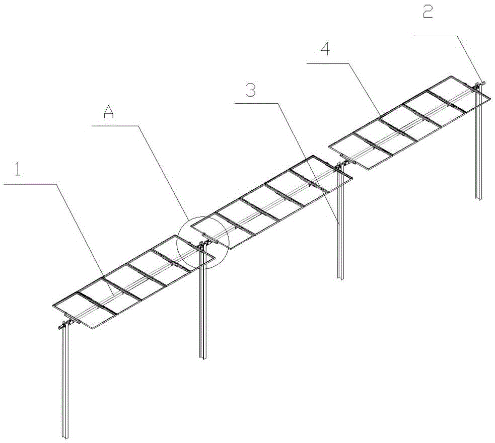
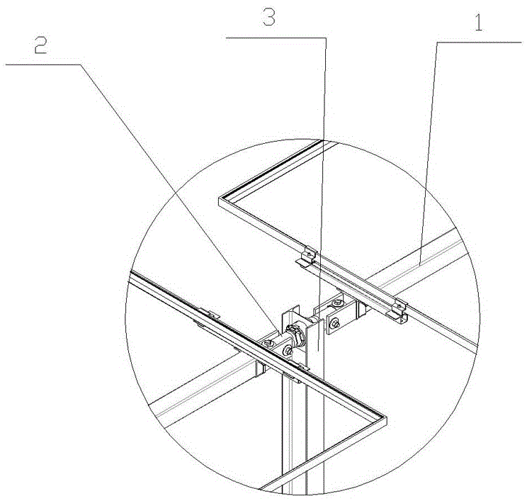
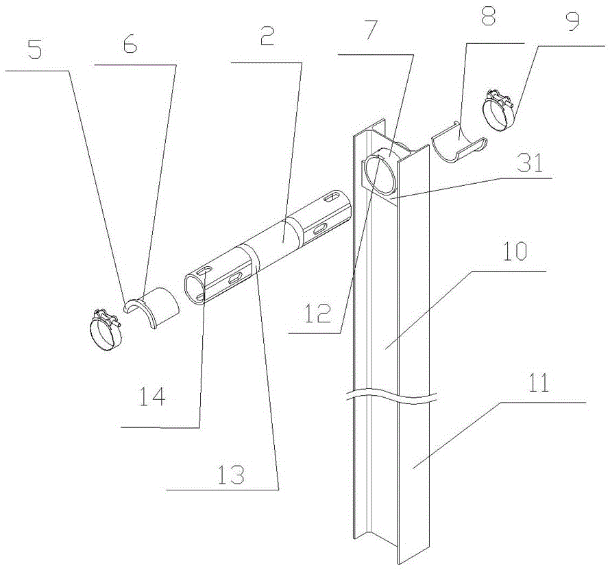
[0031] like figure 1 and 2 As shown, a solar photovoltaic module tracking device includes a column combination and a spindle combination. The column combination includes a column 3 with an "H" shape in cross section, a bearing structure, a connecting shaft 2, etc.; the spindle assembly includes a spindle 1, a beam 20, a photovoltaic module 4, and the like. Between the two columns 3 is a main shaft 1 , on which a photovoltaic module 4 is fixed, and two adjacent main shafts 1 are connected by a connecting shaft 2 , and the connecting shaft 2 is fixed on the column 3 . like image 3 As shown, the column 3 includes a column flange 10 and a column flange 11 parallel to each other on both sides of the column flange 10. A circular through hole is opened in the center of the upper end of the column flange 10, and a cylindrical bearing seat is welded in the through hole. 7. The outer edge of the bearing seat 7 is welded on the column edge plate 10. There are two rib plates 31 under ...

Embodiment 2

[0037] A method for installing a solar photovoltaic module tracking device,

[0038] The first step is to install the column combination: open a hole in the center above the column, weld the rib plate under the through hole of the column, and then weld the bearing seat. The split bearing is inserted from both ends of the bearing seat and fixed by the positioning structure. Then, a connecting shaft is inserted into the bearing, and the connecting shaft is fixed on the column by a hoop. The upper end surface of the column can still be used as the force-bearing surface of the piling equipment, and then the column with the bearing structure and the connecting shaft is driven into the ground with the piling equipment, and then the main shafts are connected together through the connecting shaft;

[0039] The second step is to install the spindle assembly: use the spindle hoop to install the beam on the connecting shaft, and then install the backing plate on the beam. Insert the nar...


PUM


Abstract

The invention relates to a photovoltaic tracker, in particular to a solar photovoltaic component tracking device and an installation method thereof. Including the column, there is a main shaft between two adjacent columns, and a photovoltaic module is arranged on the main shaft, and the two adjacent main shafts are connected by a connecting shaft, and the connecting shaft is fixed on the column, and the upper end surface of the column is the mounting surface of the column. A through hole is opened on the upper part of the shaft, and a connecting shaft is installed in the through hole through a bearing structure. A through hole is opened on the column, and the connecting shaft is installed through the bearing structure in the through hole. After pre-installation, the entire column combination is driven in by a pile driver. The invention provides a convenient installation, a simple structure, and A solar photovoltaic module tracking device and installation method that reduces the difficulty and requirements of on-site installation, shortens the installation period and cost; solves the problem that the photovoltaic module tracker in the prior art has many components, a long installation period, and high difficulty in on-site installation. Installation requires many technical issues.

Description

technical field [0001] The invention relates to a photovoltaic tracker, in particular to a solar photovoltaic component tracker and a tracker installation method. Background technique [0002] The development of new energy and renewable clean energy is a common task faced by the whole world. Among new energy sources, photovoltaic power generation has attracted much attention. However, due to the high cost, it has not yet fully entered the market. Photovoltaic power generation market has broad prospects, but the low utilization efficiency of solar energy faces the problems of high construction cost and low return on investment. At present, the installation methods for solar photovoltaic modules mainly include two types: fixed method and automatic tracking method. Using the automatic tracking method can increase the power generation by about 20% compared with the fixed method, and has broad market prospects. However, some photovoltaic module tracking devices currently resea...

Claims


Application Information

Patent Timeline
Patent Type & Authority Patents(China)
IPC IPC(8): G05D3/00
CPCF24S25/10F24S25/65F24S30/425F24S2030/136F24S2030/15H02S20/32H02S30/10Y02E10/47Y02E10/50
Inventor 杨新科朱建静郑杭丁锋军薛新颖黄旅文陈云云孙四春王敏杰
Owner VERSOLSOLAR HANGZHOU
Why Eureka
Try Eureka