
Intelligent coaxiality detection instrument

A coaxiality and detector technology, applied in the direction of instruments, measuring devices, etc., can solve the problems of general products without suitable structure and inconvenience, and achieve the effects of insufficient customer service stability, simple operation and strong comprehensiveness.

Inactive Publication Date: 2014-06-04
LUOYANG LIANGYUN PRECISION INSTR
View PDF6 Cites 7 Cited by
  • Summary
  • Abstract
  • Description
  • Claims
  • Application Information

AI Technical Summary

Problems solved by technology

[0004] It can be seen that the above-mentioned existing coaxiality detection device obviously still has inconvenience and defects in structure and use, and needs to be further improved urgently.
In order to solve the above-mentioned problems, the relevant manufacturers have tried their best to find a solution, but for a long time no suitable design has been developed, and the general product has no suitable structure to solve the above-mentioned problems. This is obviously the relevant industry. Urgent problem

Method used


Image

  • Intelligent coaxiality detection instrument
  • Intelligent coaxiality detection instrument
  • Intelligent coaxiality detection instrument

Examples


Embodiment Construction

[0046] In order to further explain the technical means and effects that the present invention takes to achieve the intended purpose of the invention, below in conjunction with the accompanying drawings and preferred embodiments, the specific implementation, structure, characteristics and details of the intelligent coaxiality detector proposed according to the present invention will be described below. Its effect is described in detail below.

[0047]The aforementioned and other technical contents, features and effects of the present invention will be clearly presented in the following detailed description of preferred embodiments with reference to the drawings. For the convenience of description, in the following embodiments, the same elements are denoted by the same numbers.

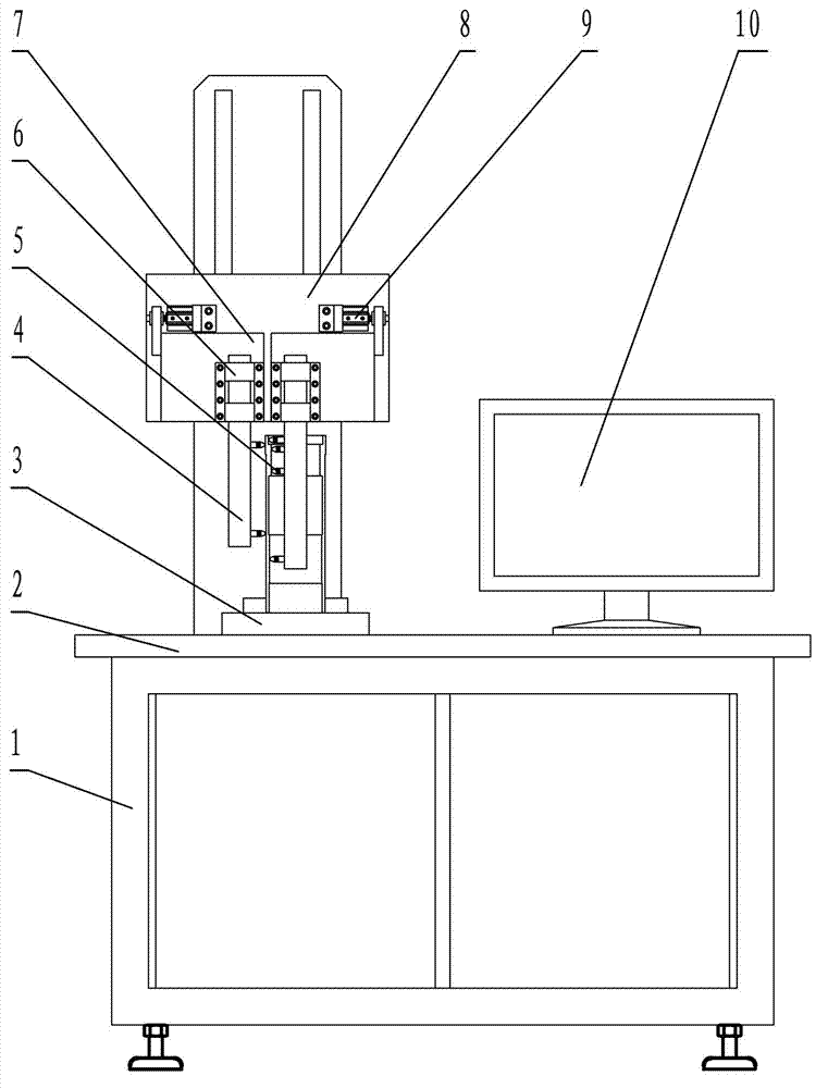
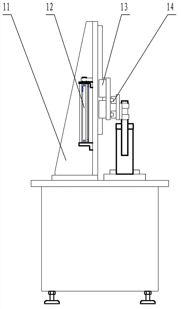
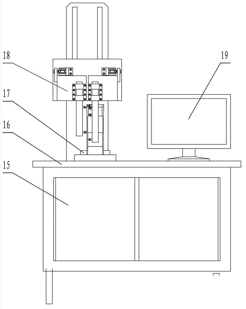
[0048] see figure 1 , figure 2 , image 3 , Figure 4 as shown, figure 1 It is a schematic front view of a specific structure of an intelligent coaxiality detector and a method thereof. figure 2...


PUM


Abstract

The invention relates to an intelligent coaxiality detection instrument and a method thereof. The intelligent coaxiality detection instrument comprises a device base, a control portion, a precise chuck, a measurement portion, a pneumatic portion and a display, wherein the control portion is arranged below the device base and integrated in a frame; the precise chuck is arranged above the device base; the measurement portion is arranged above the precise chuck and connected onto the device base; the display is arranged on one side of the measurement portion and positioned above the device base; the pneumatic portion supplies pneumatic sources to the members. Workers need to perform feeding and blanking during normal operation of the intelligent coaxiality detection instrument, and no manual intervention is needed during measurement. Furthermore, the intelligent coaxiality detection instrument is stable and reliable in measurement, strong in comprehensiveness and capable of reducing labor cost and production cost greatly and overcoming shortcoming of poor stability and large randomness errors caused by manual detection of the conventional instruments.

Description

technical field [0001] The invention relates to the detection field of coaxiality of mechanical shafts and sleeves, in particular to an intelligent coaxiality detector and detection method capable of detecting multi-section roundness and coaxiality of large and medium-sized shafts and sleeves. Background technique [0002] At present, the roundness and coaxiality detection of shafts and sleeve parts is traditional instrument detection (dial indicator with measuring tooling). This detection method can only detect the roundness and coaxiality briefly, and the detection error is relatively large. The professional requirements of the inspectors are also relatively high, and the coaxiality of the parts cannot be accurately reflected. Moreover, there is no good detection method for the coaxiality detection of large and medium-sized shafts and sleeves. However, for shafts and sleeves, further To improve the quality of the product, its roundness and coaxiality are important indicato...

Claims


Application Information

Patent Timeline
Patent Type & Authority Applications(China)
IPC IPC(8): G01B21/24
Inventor 赵曙光
Owner LUOYANG LIANGYUN PRECISION INSTR
Learn More