Lifting rod locking structure of lamps and floodlights using the lifting rod locking structure

A technology of rod lock and lamps, which is applied in the field of floodlights, can solve the problems of operation influence, loose handle, and influence on clamping operation, etc., and achieve the effect of easy installation and realization, and convenient operation

Active Publication Date: 2016-04-13
SHENZHEN OCEANS KING LIGHTING ENG CO LTD +1
View PDF4 Cites 0 Cited by
  • Summary
  • Abstract
  • Description
  • Claims
  • Application Information

AI Technical Summary

Problems solved by technology

This solution is because during the operation process, clamping the handle needs to deform the fixed seat and the movable rod. During this process, because the handle is not limited, after the handle is released, the handle is easy to rotate around the handle screw, and the handle is easy to loosen, which directly affects In the next clamping operation, in this case, to restore the clamping function, the handle must be turned back to the original position to achieve clamping, which has a great impact on the operation

Method used


Image

  • Lifting rod locking structure of lamps and floodlights using the lifting rod locking structure
  • Lifting rod locking structure of lamps and floodlights using the lifting rod locking structure
  • Lifting rod locking structure of lamps and floodlights using the lifting rod locking structure

Examples


Embodiment Construction

[0035] In order to facilitate the understanding of the present invention, the present invention will be described more fully below with reference to the associated drawings. Preferred embodiments of the invention are shown in the accompanying drawings. However, the present invention can be embodied in many different forms and is not limited to the embodiments described herein. On the contrary, these embodiments are provided to make the understanding of the disclosure of the present invention more thorough and comprehensive.

[0036] It should be noted that when an element is referred to as being “fixed” to another element, it can be directly on the other element or there can also be an intervening element. When an element is referred to as being "connected to" another element, it can be directly connected to the other element or intervening elements may also be present. The terms "vertical," "horizontal," "left," "right," and similar expressions are used herein for purposes ...


PUM


Abstract

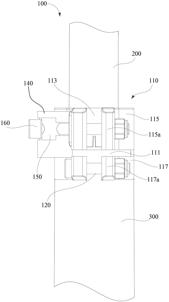
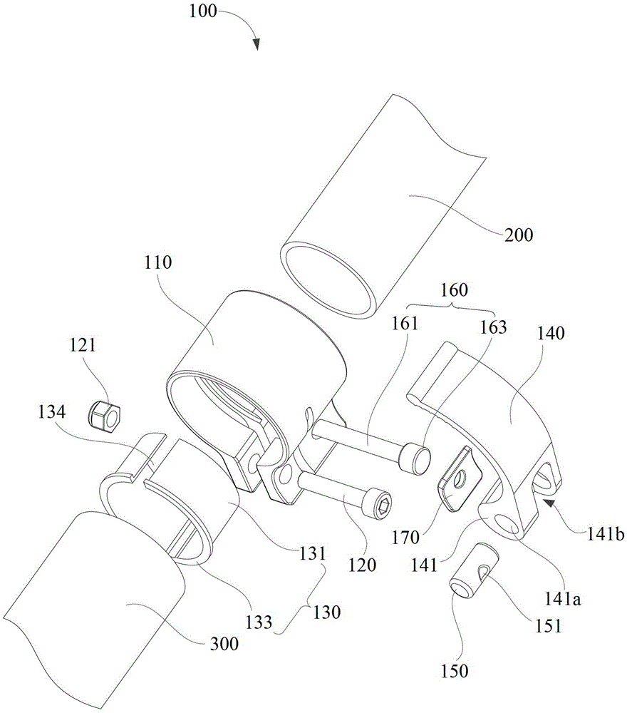
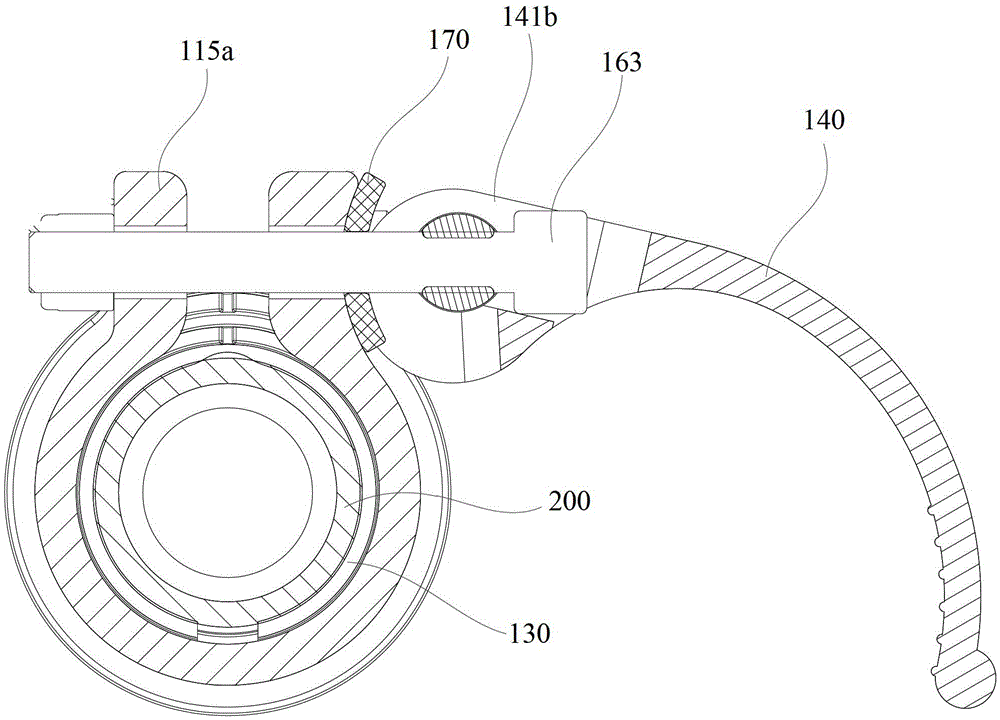
A lifting rod hasp structure for a lamp is applied to a movable rod and a bottom rod which are detachably connected and comprises a joint fixing base, a threaded fastening piece, a friction ring, a handle, a rotary shaft and a locking shaft. A first narrow groove and a second narrow groove intersecting with the first narrow groove are formed in the joint fixing base and four portions divided through the first narrow groove and the second narrow groove are two locating and clamping portions and two fixing and clamping portions; the threaded fastening piece is fixedly connected with the two fixing and clamping portions; the movable rod is sleeved with the friction ring and a third narrow groove extending in the axial direction of the friction ring is formed in the friction ring; one end of the handle is provided with an eccentric cam and a shaft hole extending in the axial direction of the eccentric cam and a limiting groove located in the middle of the eccentric cam are formed in the eccentric cam; the rotary shaft penetrates through the shaft hole of the eccentric cam; the locking shaft comprises a rod body and a stopping portion arranged at one end of the rod body, the other end of the rod body penetrates through the two locating and clamping portions, and the stopping portion is contained into the limiting groove. According to the lifting rod hasp structure, the height of the movable rod can be adjusted conveniently through the handle. The invention further provides a projection lamp with the lifting rod hasp structure.

Description

【Technical field】 [0001] The present invention relates to a locking structure, in particular to a lifting rod locking structure of a lamp and a floodlight using the lifting rod locking structure. 【Background technique】 [0002] The lifting rod structure of traditional lamps generally has multiple movable rods set together, and there is a joint fixed lock between the two movable rods, that is, one is the movable rod, the other is the bottom rod, and the gap between the movable rod and the bottom rod The joint is fixed by the lock buckle. How this articulation lock is done varies, however most articulation locks are secured with two pairs of screws and nuts. [0003] When adjusting the height of the movable rod, a special tool is needed to turn the screw, such as a handle, a screwdriver, etc. Therefore, it is difficult to unlock the locking structure of the lifting rod of the traditional lamp, which makes it inconvenient to adjust the height of the movable rod. [0004] In a...

Claims


Application Information

Patent Timeline
Patent Type & Authority Patents(China)
IPC IPC(8): F21V17/12F21S8/00
Inventor 周明杰黄剑云
Owner SHENZHEN OCEANS KING LIGHTING ENG CO LTD
Why Eureka
Try Eureka