
Fixture structure for slotting batches of plungers

A large-volume, specific structure technology, applied in the direction of grinding workpiece supports, etc., can solve the problems of increasing human resources, time-consuming and labor-intensive, and affecting processing efficiency, and achieve the effects of flexible rotation, uniform force, and reliable and convenient processing

Inactive Publication Date: 2014-05-28
无锡威孚马山油泵油嘴有限公司
View PDF4 Cites 5 Cited by
  • Summary
  • Abstract
  • Description
  • Claims
  • Application Information

AI Technical Summary

Problems solved by technology

At present, in order to meet the requirements of product drawings, it is necessary to process a long groove on the surface of the plunger. The traditional fixture structure can only meet the processing of a single long groove of the plunger. This processing method is time-consuming and laborious. It not only increases human resources, but also affects processing efficiency

Method used


Image

  • Fixture structure for slotting batches of plungers
  • Fixture structure for slotting batches of plungers
  • Fixture structure for slotting batches of plungers

Examples


Embodiment Construction

[0025] The specific implementation manner of the present invention will be described below in conjunction with the accompanying drawings.

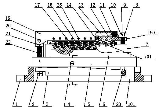
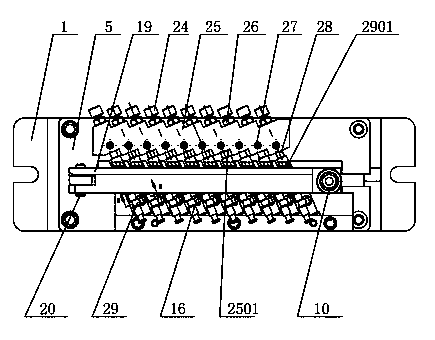
[0026] Such as figure 1 As shown, a jig structure for slotting large quantities of plungers, including a base 1, a through hole 101 is opened on the base 1, a clamp body 5 is fixed on the base 1, and pressing units are respectively arranged on the clamp body 5 , positioning unit and assembly unit;

[0027] The specific structure of the assembly unit is as follows:

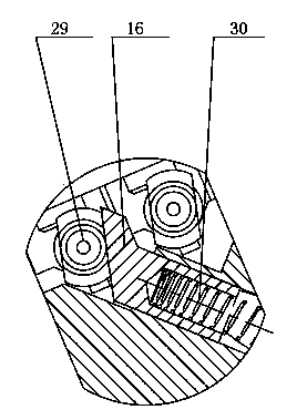
[0028] It includes a positioning plate 6 and a positioning block 7 that are connected and formed as one. The positioning block 7 is provided with a plurality of opening slots 701 arranged at intervals for installing the plunger 29; the opening slots 701 are "V" shaped, at least in the opening On an inclined surface of the groove 701, the flat position positioning column 16 is installed, such as image 3 As shown, one surface of the flat position positioning post 16 abuts aga...


PUM


Abstract

The invention relates to a fixture structure for slotting batches of plungers. The fixture structure comprises a base, wherein the base is fixedly connected with a fixture body; the fixture body is provided with a compression unit, a positioning unit and a assembly unit. The fixture structure is simple in structure and convenient to install; the assembly unit is provided with a plurality of open slots, so that batches of plungers can be assembled; positioning pillars on the positioning unit and a flat position positioning pillar are utilized for realizing the accuracy in positioning and positioning references of the plungers; a movable press plate and filled plastics in a press plate are arranged, so the stress uniformity of the plungers during machining is effectively realized; the press plate of the compression unit is flexible to rotate, so the plungers can be effectively locked and fixed, and the machining is more reliable and more convenient.

Description

technical field [0001] The invention relates to tooling, in particular to a fixture structure for slotting large quantities of plungers. Background technique [0002] The plunger couple is formed by the precision fit of the plunger and the plunger sleeve, and the oil outlet valve couple (composed of the oil outlet valve and the oil outlet valve seat) is installed above it. The plunger can be divided into different types according to the applicable fuel injection pump. Type A, Type B, Type K, Type AD, Type P, etc., to meet the needs of different diesel engines. At present, in order to meet the requirements of product drawings, it is necessary to process a long groove on the surface of the plunger. The traditional fixture structure can only meet the processing of a single long groove of the plunger. This processing method is time-consuming and laborious. It not only increases human resources, but also affects improved processing efficiency. Contents of the invention ...

Claims


Application Information

Patent Timeline
Patent Type & Authority Applications(China)
IPC IPC(8): B24B41/06
CPCB24B41/06
Inventor 徐俊伟
Owner 无锡威孚马山油泵油嘴有限公司
Learn More