Auxiliary power tool handle

一种动力工具、把手的技术,应用在辅助动力工具把手领域,能够解决破裂、工具的齿片弯曲、扭曲等问题

Inactive Publication Date: 2014-05-21
SNAP ON INC
View PDF7 Cites 4 Cited by
  • Summary
  • Abstract
  • Description
  • Claims
  • Application Information

AI Technical Summary

Problems solved by technology

Thus, this conventional structure causes hand and wrist discomfort and ultimately causes the teeth of the tool to bend, twist and break

Method used


Image

  • Auxiliary power tool handle
  • Auxiliary power tool handle
  • Auxiliary power tool handle

Examples


Embodiment Construction

[0016] The invention is susceptible to embodiments in many different forms, and the drawings show and describe preferred embodiments of the invention, and it should be understood that the disclosure should be considered as exemplifying the principles of the invention and that the illustrated embodiments do not constitute a Limitation on Scope of Invention.

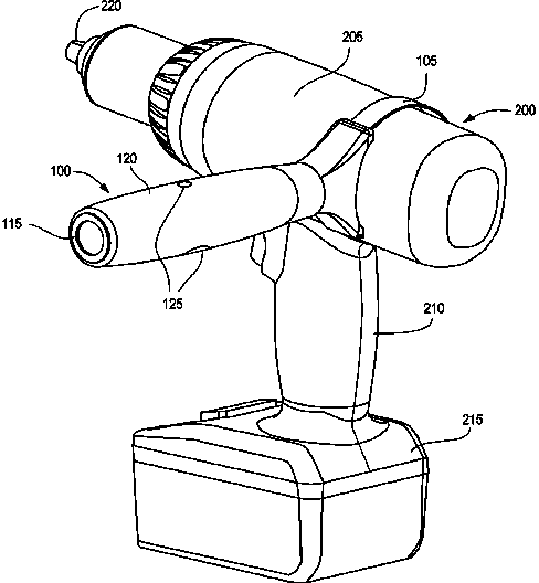
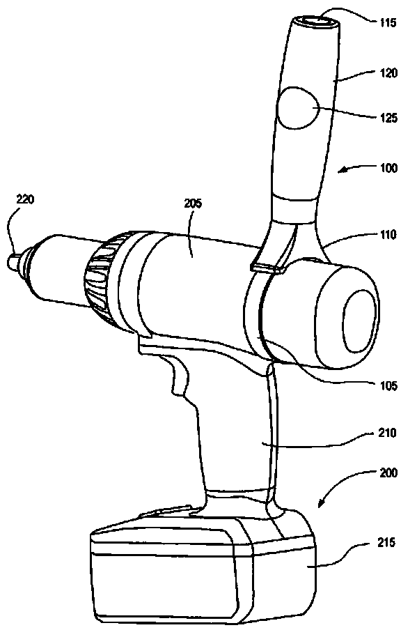
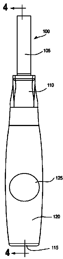
[0017] The present application discloses a handle that can be constructed in a straight or T-shaped position based on the user's preference. In the straight position, the handle enables the user to control the rotational force of the tool, and, in the T-shaped configuration, the user can more easily apply rotational and longitudinal forces because the handle is positioned tangential to the tool body. The handle is easily adjustable from a straight line to a T-shaped position and is also removable from the power tool if the user so chooses.

[0018] Such as Figure 1-3 As shown, the handle 100 is connected to the power to...


PUM


Abstract

A handle for controlling a power tool by configuring the handle in either a straight or T-shaped position. In the straight position, the handle design serves as a rotational safety control that allows a user to control the rotational reaction of the tool by placing the user's hand in a position that is perpendicular to the main body of the tool. In the T-shaped configuration, the user can apply rotational force and longitudinal force more easily because the hand position is tangent to the tool base. A fastener couples a base of the handle to a band that grips the power tool and facilitates the user control.

Description

technical field [0001] This application generally relates to handles for power tools. More specifically, the present application relates to auxiliary power tool handles that are adjustable into straight or T-shaped configurations. Background technique [0002] Power tools are often used for complete industrial systems or home improvement tasks. Many power tools are portable and battery powered, enabling the user to apply considerable torque or force to a workpiece without applying enormous amounts of energy. However, many power tools generate significant vibration and rotational force when in use, or can be difficult to control due to the amount of power transmitted from the tool to the workpiece or work carrier. [0003] Several attempts have been made to solve the above problems. For example, handles have been studied that allow a user to hold a power tool with one hand and control the motion of the power tool by holding the handle with the other hand. Typically, the h...

Claims


Application Information

Patent Timeline
Patent Type & Authority Applications(China)
IPC IPC(8): B25G1/00
CPCB25F5/026F16B2/08F16B7/0493F16B2200/403B25G1/00
Inventor 保罗·W·格里芬
Owner SNAP ON INC
Why Eureka
Try Eureka