Starting control method for input-series output-quasi-parallel multiplexed output converter
A multi-channel output and series output technology, applied in the direction of output power conversion devices, electrical components, etc., can solve problems such as excessive starting voltage and starting current, DC-DC damage, overvoltage, etc., to avoid excessive input voltage Effect
- Summary
- Abstract
- Description
- Claims
- Application Information
AI Technical Summary
Problems solved by technology
Method used
Image
Examples
Embodiment 1
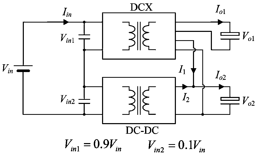
[0025] as attached image 3 As shown, when starting, in order to prevent the main power from being directly applied to both ends of the DC-DC converter, the DCX and DC-DC drivers can be turned off when the main power is first added, and their duty ratios are set to zero, so that The input voltage of DCX and DC-DC will be established slowly according to the relationship of the input voltage dividing capacitor. The voltage dividing capacitor adopts 1:9 distribution to ensure that the input voltage of DC-DC is one-tenth of that of the main power supply, and the input voltage of DCX is nine-tenths of that of the main power supply. At the same time, for the convenience of analysis, the case where DCX has two outputs is considered here, as shown in the attached image 3 shown. When DCX is multi-output with image 3 The control principle of the two outputs is the same.
[0026] image 3 , the auxiliary power supply of the microcontroller is controlled by V in obtained after tra...
Embodiment 2
[0036] The flow chart of start-up control of the present invention is as attached Figure 5 Shown, the control process of the present invention is as follows:
[0037] 1) The auxiliary supply is supplied by V in obtained after transformation, when the main voltage V in When it comes, the auxiliary power supply starts to work and supplies power to the single-chip microcomputer. The single-chip microcomputer first initializes DCX and DC-DC, and sets the switching frequency of DCX f s_DCX =450kHz, DC-DC switching frequency f DC_DC =90kHz, and the duty cycles of both DCX and DC-DC are zero. Set the value of sampling reference voltage corresponding to 3V output voltage.
[0038] 2) After the input voltage is established, the PWM interrupt is turned on, and the system enters closed-loop regulation. The MCU defines the flag bit Flag=0. In the interrupt program, set the duty cycle of DCX to a smaller value D DCX =0.1, the output voltage is stable at 3V output;
[0039] 3) Afte...
PUM
 Abstract
Description
Claims
Application Information
 - R&D
- Intellectual Property
- Life Sciences
- Materials
- Tech Scout
- Unparalleled Data Quality
- Higher Quality Content
- 60% Fewer Hallucinations
Browse by: Latest US Patents, China's latest patents, Technical Efficacy Thesaurus, Application Domain, Technology Topic, Popular Technical Reports.
© 2025 PatSnap. All rights reserved.Legal|Privacy policy|Modern Slavery Act Transparency Statement|Sitemap|About US| Contact US: help@patsnap.com


