
Chained hybrid energy storage system with LC tuned filter and control method thereof

A hybrid energy storage system, chain-type technology, applied to harmonic reduction devices, AC networks to reduce harmonics/ripples, energy storage, etc., can solve high cost, difficult supercapacitor energy, weak power output capacity of batteries, etc. problem, to achieve the effect of power exchange

Inactive Publication Date: 2014-05-21
SOUTHEAST UNIV
View PDF4 Cites 8 Cited by
  • Summary
  • Abstract
  • Description
  • Claims
  • Application Information

AI Technical Summary

Problems solved by technology

However, due to the series structure between the converters, the energy storage unit of the battery and the energy storage unit of the supercapacitor need to have the same current output capability, which is contradictory to the characteristics that the supercapacitor has a strong current output capability and the battery power output capability is weak
At the same time, the output voltage and the number of levels are directly related to the number of energy storage units connected in series, and the output of high voltage and low harmonic voltage requires more energy storage elements and higher cost
Finally, in a series configuration, the energy in the supercapacitor is difficult to replenish from the battery

Method used


Image

  • Chained hybrid energy storage system with LC tuned filter and control method thereof
  • Chained hybrid energy storage system with LC tuned filter and control method thereof
  • Chained hybrid energy storage system with LC tuned filter and control method thereof

Examples


Embodiment Construction

[0033] The present invention will be described in detail below in conjunction with the accompanying drawings and embodiments.

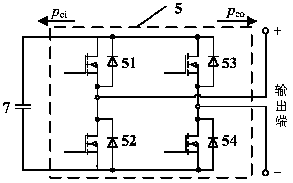
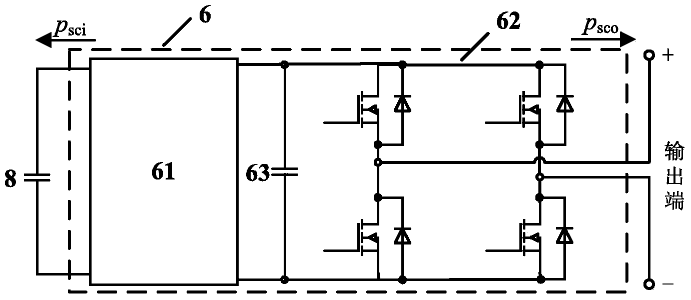
[0034] Such as figure 1 A chain-type hybrid energy storage system is shown, including several supercapacitor energy storage units, several battery energy storage units, several capacitor power units, output inductor 1, AC bus 2, LC tuned filter 3, current detection unit 4 , voltage detection unit 10 and controller 11 . Wherein: each supercapacitor energy storage unit is composed of a supercapacitor 8 correspondingly connected in parallel with an input terminal of a cascade converter 6 . Each battery energy storage unit is composed of a battery 9 correspondingly connected in parallel with an input end of a cascaded converter 6 . Each capacitor power unit is composed of a capacitor 7 connected in parallel with a full-bridge converter 5 . All supercapacitor energy storage units, battery energy storage units, and capacitor power units form a chain hybr...


PUM


Abstract

The invention discloses a chained hybrid energy storage system with an LC tuned filter and a control method thereof. The chained hybrid energy storage system comprises a chained hybrid energy storage structure formed by a capacitor power unit, a super capacitor energy storage unit and a storage battery energy storage unit, and the LC tuned filter which is connected with the chained hybrid energy storage structure so as to form an auxiliary power loop circuit. The chained hybrid energy storage system controls each unit by outputting a PWM (pulse width modulation) modulating wave, wherein the modulating wave is composed of two portions which are respectively a power frequency modulating wave and a high frequency modulating wave. The power frequency modulating wave controls power frequency alternating voltage and current output of the energy storage system. The high frequency modulating wave controls power to transfer among all the units through the auxiliary power loop circuit, wherein the super capacitor energy storage unit charges the capacitor power unit through the auxiliary power loop circuit so as to keep terminal voltage of the capacitor power unit stable, when current output of the storage battery energy storage unit is insufficient, the super capacitor energy storage unit provides the power for the storage battery energy storage unit through the auxiliary power loop circuit, and when residual energy of a super capacitor is insufficient, a storage battery charges the super capacitor through the auxiliary power loop circuit.

Description

technical field [0001] The invention relates to the technical field of energy storage, in particular to a chain hybrid energy storage system and a control method thereof. Background technique [0002] Existing energy storage elements can be divided into two types: energy type (lead-acid battery, lithium battery and sodium-sulfur battery, etc.) and power type (supercapacitor, superconducting magnetic energy storage, flywheel energy storage, etc.). Certain requirements in practical applications, such as smoothing intermittent power fluctuations, require the energy storage system to have both a fast response part and a certain energy storage capacity, so it is difficult to meet only one type of energy storage technology. The Hybrid Energy Storage System (HESS) can complement the characteristics of different energy storage technologies by directly connecting different types of energy storage components in parallel or through power electronic converters, thereby improving the ove...

Claims


Application Information

Patent Timeline
Patent Type & Authority Applications(China)
IPC IPC(8): H02J3/32H02J3/01
CPCY02E40/40Y02E70/30
Inventor 蒋玮胡仁杰丁一阳黄慧春
Owner SOUTHEAST UNIV
Learn More