
Single-arm manipulator

A manipulator and single-arm technology, applied in the field of robotics, can solve problems such as occupying a large space and narrow working space

Active Publication Date: 2014-05-21
SHENYANG SIASUN ROBOT & AUTOMATION
View PDF6 Cites 4 Cited by
  • Summary
  • Abstract
  • Description
  • Claims
  • Application Information

AI Technical Summary

Problems solved by technology

[0004] In order to improve the utilization rate of space, the current workstation space is relatively small, and the existing manipulator needs to occupy a large space when running

Method used


Image

  • Single-arm manipulator
  • Single-arm manipulator
  • Single-arm manipulator

Examples


Embodiment Construction

[0011] Embodiments of the present invention are described in detail below, examples of which are shown in the drawings, wherein the same or similar reference numerals designate the same or similar elements or elements having the same or similar functions throughout. The embodiments described below by referring to the figures are exemplary only for explaining the present invention and should not be construed as limiting the present invention.

[0012] In the description of the present invention, the orientation or positional relationship indicated by the terms "inner", "outer", "longitudinal", "transverse", "upper", "lower", "top", "bottom" etc. are based on the drawings The orientations or positional relationships shown are only for the convenience of describing the invention and do not require the invention to be constructed and operated in a specific orientation, and thus should not be construed as limitations on the invention.

[0013] see figure 1 as well as figure 2 , ...


PUM


Abstract

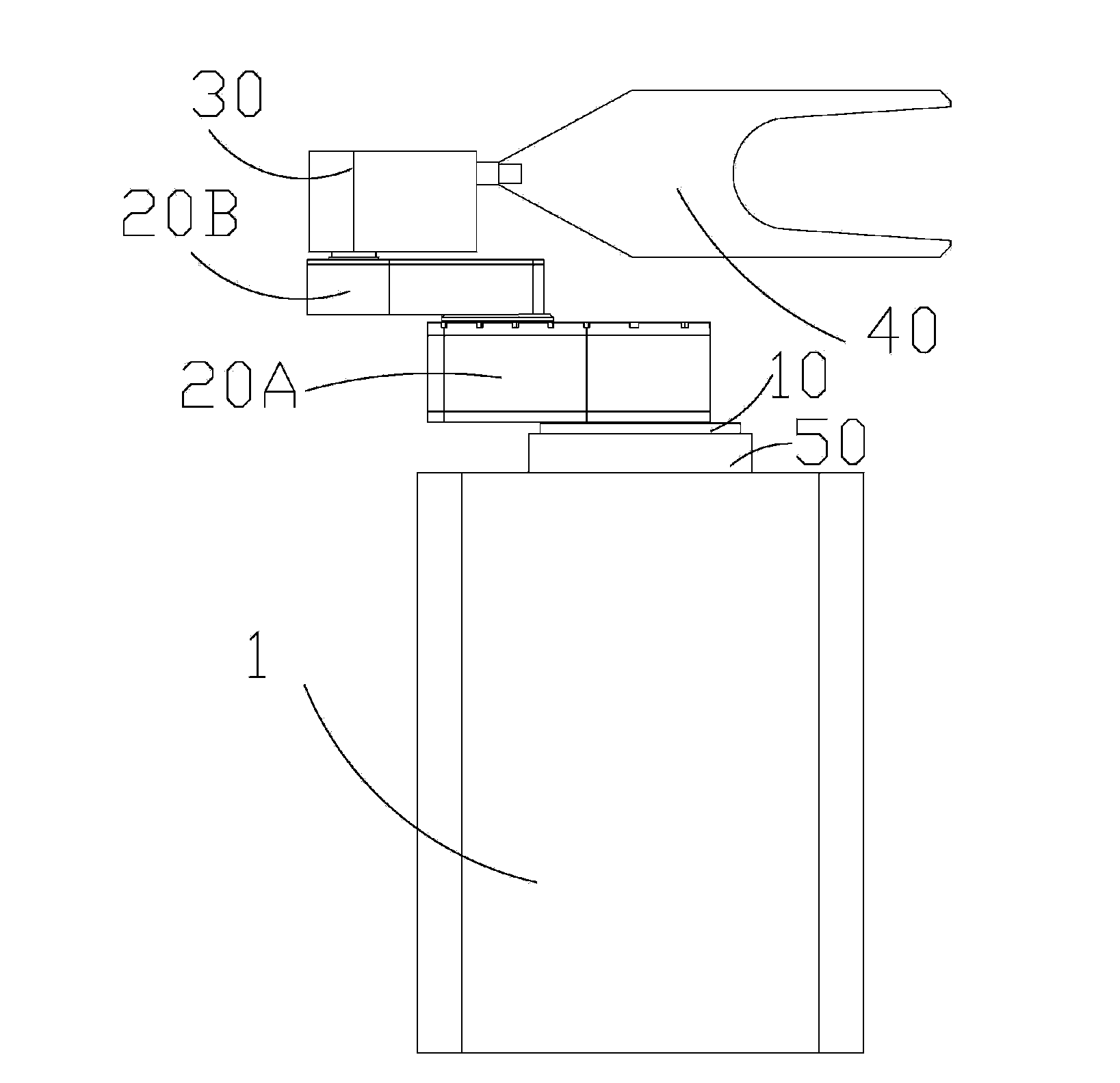
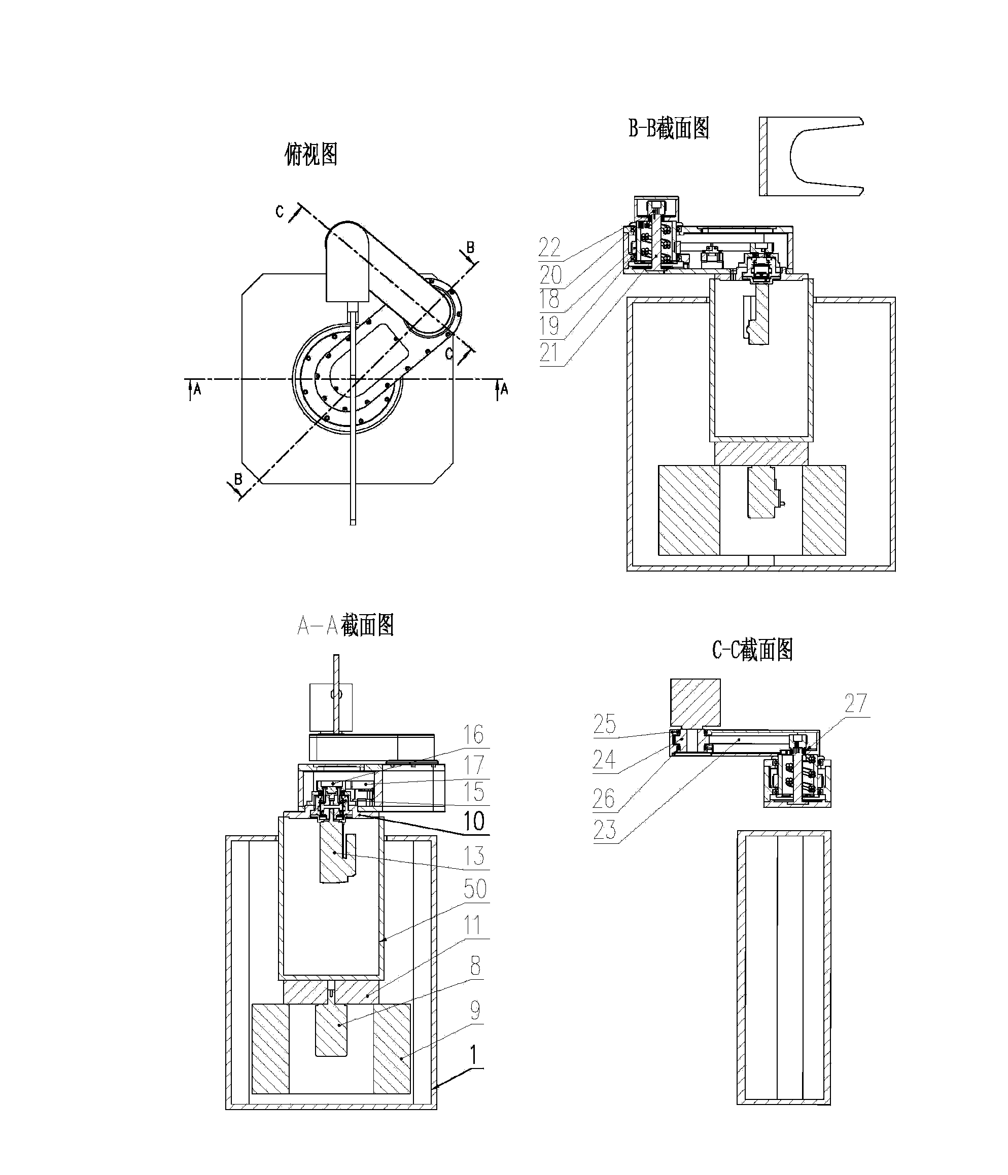
The invention provides a single-arm manipulator. The manipulator comprises a column, a waist seat, a connecting fitting, a first arm, a second arm, an end member, a clamping claw, a first motor and a second motor, wherein the first arm and the second arm comprise butt ends and thin ends; the cylindrical connecting fitting is located in the column; the waist seat is in the shape of a flat plate, and the bottom of the waist seat is fixedly connected with the connecting fitting; the butt end of the first arm is fixedly connected with the waist seat, the thin end of the first arm is movably connected with the butt end of the second arm, and the thin end of the second arm is movably connected with the end member; the clamping claw which is roughly in a Y-shape is movably connected with the end member; the first motor and the second motor are in coupling motion to drive the first arm and the second arm in common and control the end member to perform rectilinear motion. The single-arm manipulator of the invention is small in occupied space and high in space utilization rate.

Description

[0001] technical field [0002] The invention relates to a robot, in particular to a single-arm manipulator. Background technique [0003] With the in-depth development of automation technology, factories have put forward higher requirements for the degree of automation of plate-shaped workpieces. In existing semiconductor factories, robots are generally used to carry wafers on the workstations, and perform operations such as cleaning or grinding the wafers. Currently, the manipulator is installed in the machine, and the workstations are located in the machine. [0004] In order to improve the utilization rate of space, the current workstation space is relatively small, and the existing manipulator needs to occupy a large space when it is running. Contents of the invention [0005] In view of this, it is necessary to provide a single-arm manipulator that can move in a narrow space. [0006] The single-arm manipulator in the embodiment of the present invention includes: a ...

Claims


Application Information

Patent Timeline
IPC IPC(8): B25J9/00B25J9/08
Inventor 徐方朱维金王凤利朱玉聪徐传胜曲道奎
Owner SHENYANG SIASUN ROBOT & AUTOMATION
Learn More