
Intravenous drip automatic monitoring system

A monitoring system and drip technology, applied in the field of medical equipment, to prevent blood return, reduce running pressure, and facilitate needle withdrawal

Inactive Publication Date: 2014-05-21
HARBIN BO QIANG ROBOT TECH CO LTD
View PDF10 Cites 15 Cited by
  • Summary
  • Abstract
  • Description
  • Claims
  • Application Information

AI Technical Summary

Problems solved by technology

[0005] The purpose of the present invention is to solve the problems existing in the existing drip monitoring device and provide a drip automatic monitoring system

Method used


Image

  • Intravenous drip automatic monitoring system
  • Intravenous drip automatic monitoring system
  • Intravenous drip automatic monitoring system

Examples


specific Embodiment approach 1

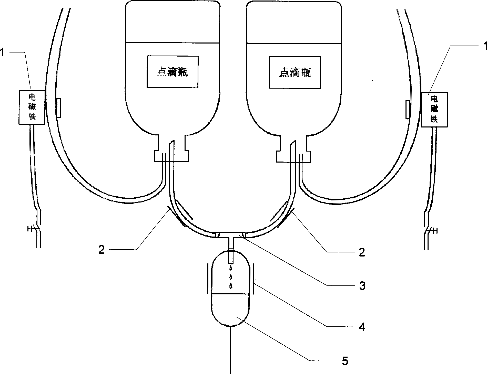
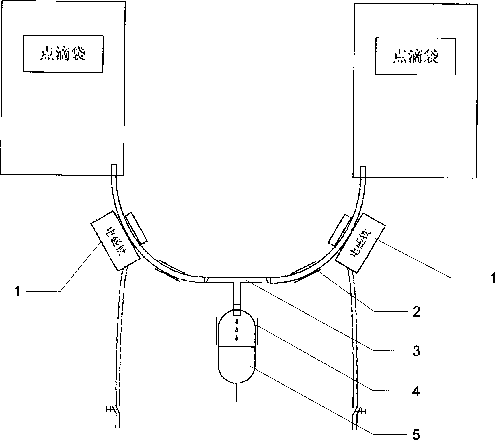
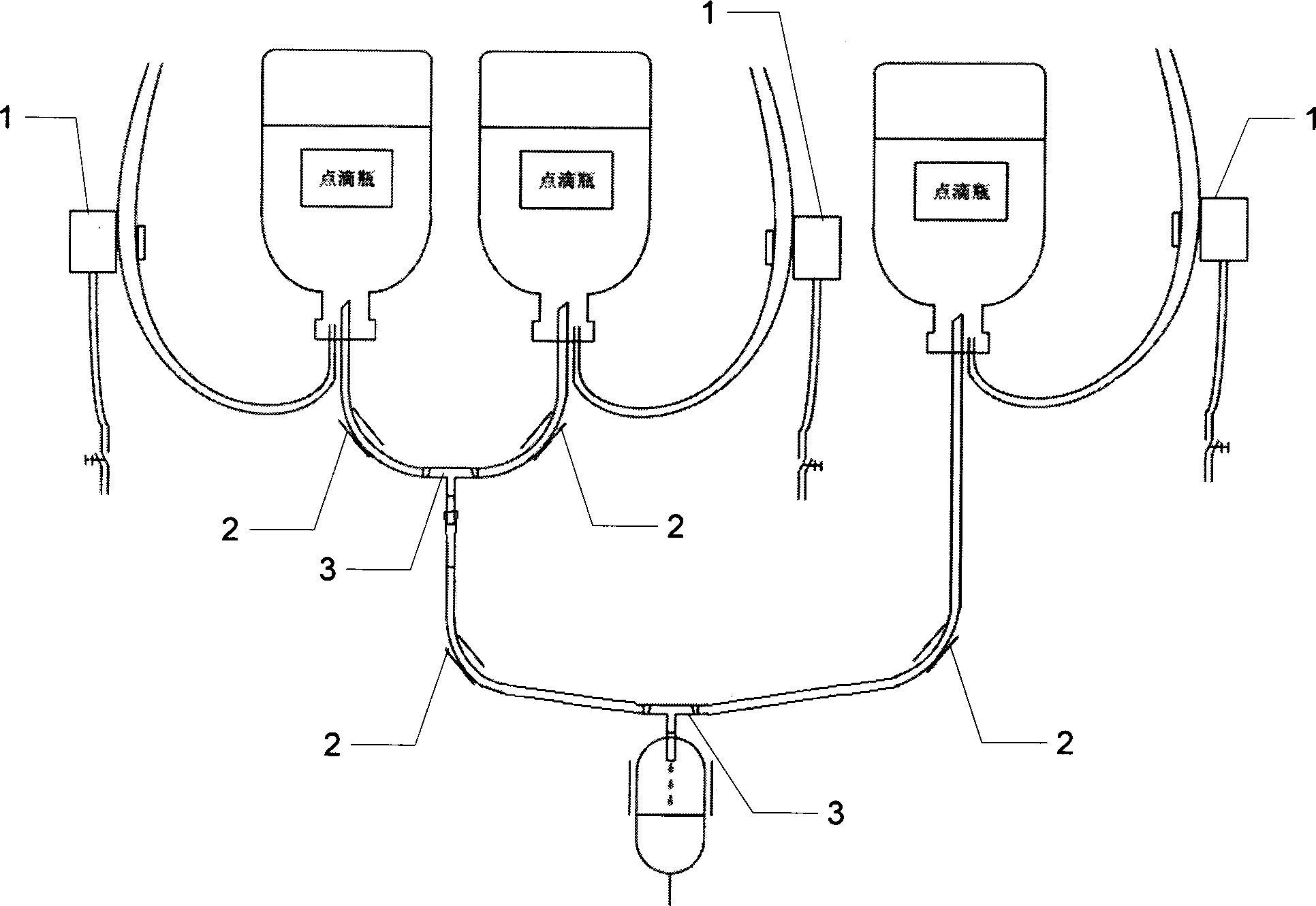
[0031] Specific implementation mode one: the following combination Figure 1 to Figure 4 Describe this embodiment mode, a kind of drip automatic monitoring system described in this embodiment mode, it comprises host computer, k nurse terminal and m*k drip control device;

[0032] When dripping each patient, n groups of medicinal liquids are required to be infused sequentially, and the n groups of medicinal liquids are respectively placed in n groups of medicinal liquid containers, and the n groups of medicinal liquid containers are connected to the intravenous drip via n-1 three-way valves (3). The pipe (5) is connected;

[0033] Each infusion control device is used to monitor the infusion status of a patient, and send the patient's infusion completion status to the host computer and the nurse terminal in charge of the infusion control device;

[0034] Each nurse terminal is responsible for monitoring m drip control terminals, and each drip control terminal communicates with ...

specific Embodiment approach 2

[0039] Specific implementation mode two: the following combination figure 1 and figure 2 This embodiment will be described. This embodiment will further describe Embodiment 1, and the liquid medicine container is a drip bottle.

[0040] When the patient only needs one kind of medicinal solution, the three-way valve 3 is not needed. If the patient needs to instill two kinds of medicinal solutions sequentially, a three-way valve 3 is needed, such as figure 1 As shown; if the patient needs to instill three kinds of medicinal liquids sequentially, two three-way valves 3 are needed, and the connection method is as follows figure 2 shown.

specific Embodiment approach 3

[0041] Specific implementation mode three: the following combination image 3 This embodiment will be described. This embodiment will further describe Embodiment 1, and the medical solution container is an drip bag.


PUM


Abstract

The invention discloses an intravenous drip automatic monitoring system, and belongs to the field of medical apparatus and instruments. The intravenous drip automatic monitoring system aims to solve the problems that an existing device for generating radially polarized beams and azimuthally polarized beams is complex in structure and high in cost. The intravenous drip automatic monitoring system comprises an upper computer, k nurse terminals and m*k intravenous drip control devices. When each patient is on an intravenous drip and needs to be infused with n sets of drug solutions in sequence, the n sets of drug solutions are placed in n sets of drug solution containers respectively, and the n sets of drug solution containers are communicated with an intravenous drip pipe through n-1 three-way valves; each intravenous drip control device is used for monitoring the intravenous drip state of the corresponding patient and sending the intravenous drip finishing state of the patient to the upper computer and the corresponding nurse terminal which is in charge of the intravenous drip control device; each nurse terminal is in charge of monitoring the m intravenous drip control terminals, and all the intravenous drip control terminals communicate with the upper computer. The intravenous drip automatic monitoring system has the advantages that nurses can be automatically informed of the intravenous drip state, blood return can be automatically avoided, special accompanying relatives are not needed, and rest of the patients is not affected.

Description

technical field [0001] The invention relates to an automatic drip monitoring system, which belongs to the field of medical equipment. Background technique [0002] Drip is a routine job in the hospital, with a heavy workload and heavy tasks, especially in summer and autumn when diseases frequently occur. If the patient does not pay attention and the nurse cannot deal with it in time, problems such as blood relapse will cause harm to the patient. [0003] Some monitoring automatic alarm invention devices are arranged now, can report to the police when drip medicinal liquid does not have. The one, these alarm devices can not tell the nurse specific location, the 2nd, can not guarantee that the nurse knows in time, the 3rd, can not handle automatically, can't fundamentally solve the problem. [0004] There are also some complex control system inventions, which are costly and not practical, and cannot be practically applied and promoted. Contents of the invention [0005] Th...

Claims


Application Information

Patent Timeline
IPC IPC(8): A61M5/168A61M5/36
Inventor 孔民秀祝宇虹
Owner HARBIN BO QIANG ROBOT TECH CO LTD
Learn More