Vertical lifting and unloading working device of loader

A vertical lift and loader technology, applied in the direction of mechanically driven excavators/dredgers, etc., can solve the problems of reducing the working efficiency of the loader working device, affecting the flexibility and stability of the equipment, affecting the lifting height and distance, etc. The effect of compact structure, enlarged rise height, and improved work efficiency

Inactive Publication Date: 2014-05-14
QINGDAO LUDA PROJECT MACHINE MFR
View PDF0 Cites 6 Cited by
  • Summary
  • Abstract
  • Description
  • Claims
  • Application Information

AI Technical Summary

Problems solved by technology

At present, the working device of the loader mainly consists of a boom, a connecting rod, a rocker arm, a bucket turning cylinder, a boom cylinder, and a fixed bracket. The fixed bracket is fixed on the car body. For small loaders, the fixed bracket is also fixed on the On the rear side of the front axle, the rear end of the boom is connected to the fixed bracket through the hinge shaft at the upper end of the fixed bracket, and the fixed bracket and the boom are connected by the boom cylinder at the appropriate position of the boom. During the lifting process of the working device, due to The seat end of the boom rotates along the fixed hinge shaft. Under the action of the telescopic rod of the boom cylinder, the lifting and lowering running track of the front hinge shaft of the boom and the bucket is an arc, and the arc track starts from the seat end of the boom. The fixed articulated shaft is the center of the circle. Since the articulated shaft at the seat end of the boom is immovable, this arc track is also fixed. The working device with this structure has the following disadvantages: First, in order to expand the range of motion of the boom, its The boom needs to be made very long, and when it is lowered to the lower part, the distance that the front hinged shaft of the boom extends out of the frame is too long, which makes the whole machine longer and affects the flexibility and stability of the equipment; the second is when the bucket When the boom is raised from the horizontal position to the highest position, the front hinge shaft of the boom and the bucket have a certain retraction distance along the arc track, so the loading and unloading distance of the loader becomes smaller and the working efficiency of the loader working device is reduced , affecting the rising height and distance, this shortcoming is more obvious on small loaders

Method used


Image

  • Vertical lifting and unloading working device of loader
  • Vertical lifting and unloading working device of loader
  • Vertical lifting and unloading working device of loader

Examples


Embodiment Construction

[0010] The present invention will be described in further detail below in conjunction with the accompanying drawings and specific embodiments.

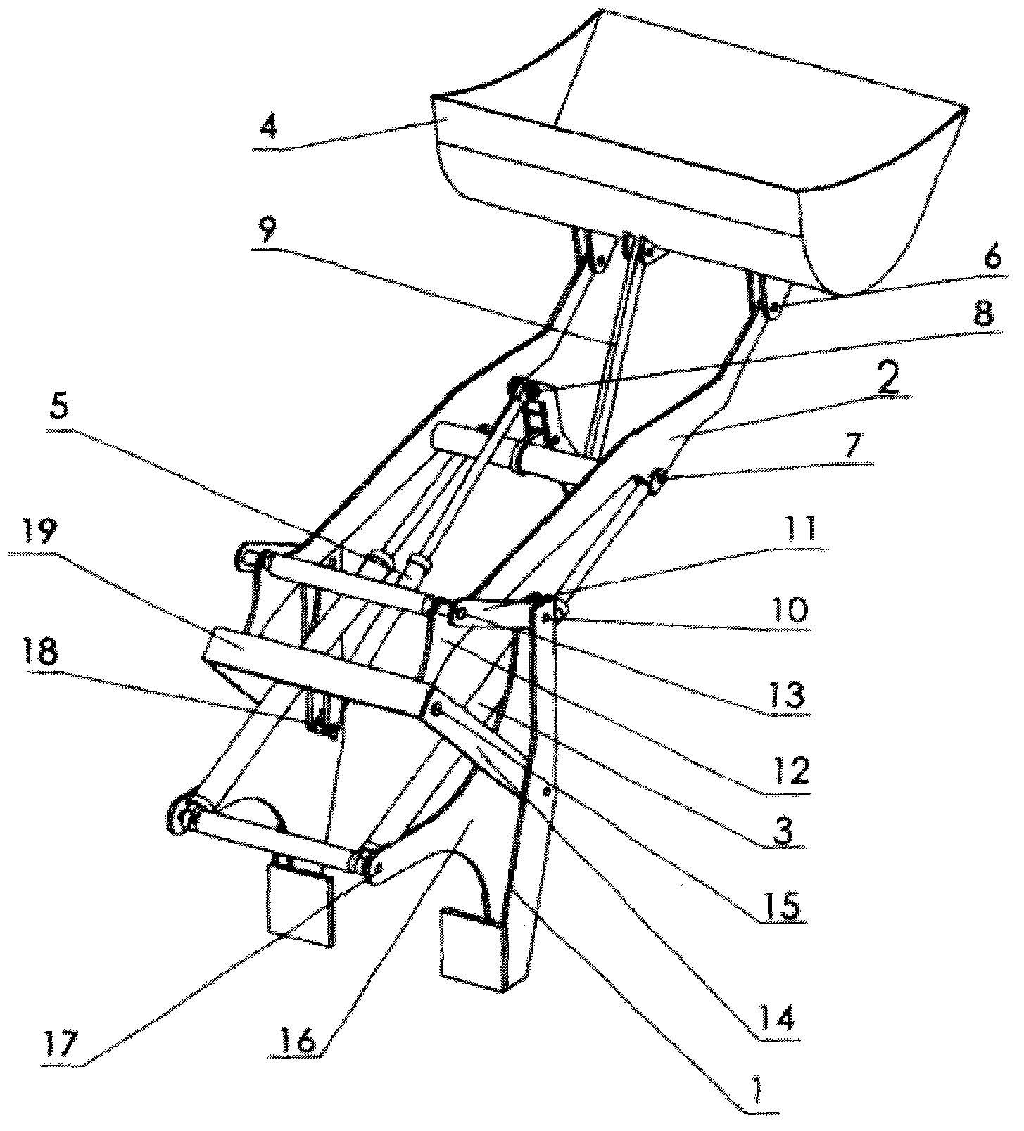
[0011] Such as figure 1 figure 2 image 3 Figure 4 As shown, the vertical lifting and unloading working device of the loader is composed of a fixed bracket 1, a boom 2, a boom cylinder 3, a bucket 4, and a bucket turning cylinder 5; the front end of the boom 2 is hinged through the bottom of the bucket 6 Connected to the bottom of the bucket 4, the front end of the telescopic rod of the boom cylinder 3 is connected to the middle of the boom 2 through the hinge shaft 7 in the middle of the boom, and the front end of the telescopic rod of the bucket flip cylinder 5 passes through the hinge shaft 8 at the rear end of the flip connecting rod 9 It is connected with the flip link 9 on the rear side of the bucket 4, and the upper rotating handle 11 is connected to the upper part of the fixed bracket 1 through the hinge shaft 10 at the u...


PUM


Abstract

The invention discloses a vertical lifting and unloading working device of a loader. The vertical lifting and unloading working device comprises a fixing support, movable arms, movable arm cylinders, a bucket and a bucket turnover cylinder. The front ends of the movable arms are connected to the bottom of the bucket, and the front ends of the movable arm cylinders are connected to the middles of the movable arms. The vertical lifting and unloading working device is characterized in that upper rotary handles are arranged on the upper portion of the fixing support, shifting rods are arranged at the rear ends of the movable arms, lower rotary handles are arranged in the middle of the fixing support, and the upper rotary handles, the lower rotary handles, the shifting rods and the upper section of the fixing support form four-bar linkage mechanisms. The vertical lifting and unloading working device has the advantages that the movable arms can rotate and translate in lifting procedures, so that the bucket can be vertically lifted in a running path of the bucket, the work efficiency of the loader can be improved, and the lifting height and the unloading distance of a working mechanism of the loader can be increased; the vertical lifting and unloading working device is compact in structure and particularly suitable for small loaders, and can run stably.

Description

technical field [0001] The invention relates to the field of loaders, in particular to a loader vertical lifting and unloading working device. Background technique [0002] The working device of the loader is the key mechanism to complete the loading and unloading operation, and its structural form can directly relate to the work efficiency and economic indicators of the loader. At present, the working device of the loader mainly consists of a boom, a connecting rod, a rocker arm, a bucket turning cylinder, a boom cylinder, and a fixed bracket. The fixed bracket is fixed on the car body. For small loaders, the fixed bracket is also fixed on the On the rear side of the front axle, the rear end of the boom is connected to the fixed bracket through the hinge shaft at the upper end of the fixed bracket, and the fixed bracket and the boom are connected by the boom cylinder at the appropriate position of the boom. During the lifting process of the working device, due to The seat ...

Claims


Application Information

Patent Timeline
IPC IPC(8): E02F3/36E02F3/38E02F3/42
Inventor 付文君傅稼浩刘浩
Owner QINGDAO LUDA PROJECT MACHINE MFR
Why Eureka
Try Eureka