Washing machine damping support structure and washing machine
A technology of supporting structure and washing machine, applied in the field of washing machines, can solve the problems of high rigidity of the middle box of the washing machine, mismatch of installation positions of consoles, difficult installation, etc., and achieves the effects of average force, reasonable stress distribution, and simplified production.
- Summary
- Abstract
- Description
- Claims
- Application Information
AI Technical Summary
Problems solved by technology
Method used
Image
Examples
Embodiment 1
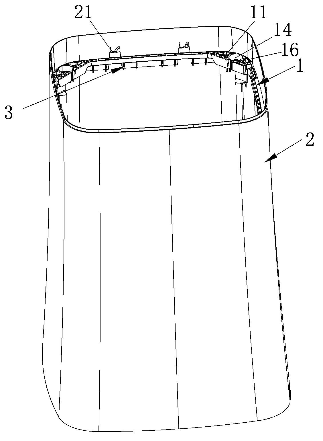
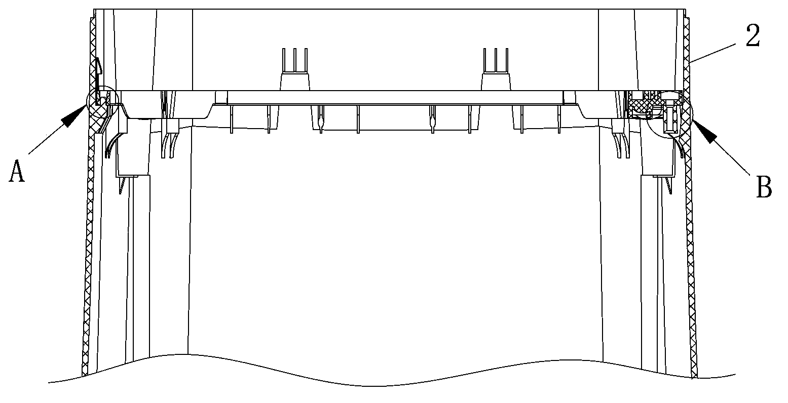
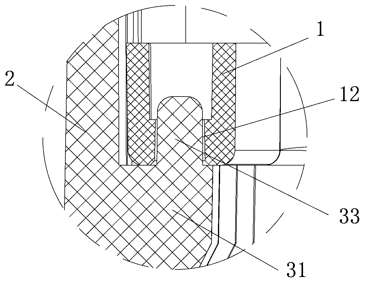
[0034] Such as Figure 2 to Figure 4 As shown, a positioning structure is provided between the support frame 1 and the support member 3 described in this embodiment, including the positioning column 33 provided on the support rib 31 and the positioning hole 12 provided on the support frame 1, at least one support protrusion The rib 31 is provided with a positioning post 33 , and the support frame 1 is provided with a corresponding positioning hole 12 . There are eight groups of positioning structures, and each group is arranged on a side wall of the inner wall around the box body.
[0035] The supporting ribs 31 on which the positioning columns 33 are set are arranged at intervals on the inner wall of the box body 2. Two supporting ribs 31 form a group, and the distance between the two supporting ribs 31 in the same group is smaller than that of the two groups of supporting ribs. distance between ribs. The structure uses the characteristics of concentrated force support at o...
Embodiment 2
[0037] Such as Figure 5 with Figure 7 As shown, the box body 2 described in this embodiment includes four side walls (refer to figure 1), the arc transition at the bend, the support frame 1 matches the inner wall of the box body 2, the four corners of the support frame 1 are respectively provided with reinforcements 13, the reinforcement 13 is provided with a semi-spherical groove 14, and the bottom of the groove 14 is provided with a through The hole 15 is provided with a gap 16 communicating with the through hole 15 in the direction corresponding to the inside of the support frame 1 to install the shock-absorbing boom. Preferably, the clearance of the gap 16 is designed according to the diameter of the vibration-damping boom and is suitable for the installation of the shock-absorbing boom.
[0038] A plurality of reinforcing ribs 17 arranged radially along the through hole 15 are provided below the support frame groove 14, and this structure can strengthen the shock-absor...
Embodiment 3
[0041] Such as Figure 7 As shown, the support frame 1 described in this embodiment is provided with reinforcing ribs 18 and wiring harness positioning cards 19, the reinforcing ribs 18 are distributed along the frame body, and the wiring harness positioning cards 19 extend from the inner wall of the supporting frame to the center of the supporting frame, and the ends are The C-shaped structure elastic card at the movable end, the bottom such as the connection line from the drive mechanism to the upper control board and other wiring harnesses that move up and down are fixed in the wiring harness positioning card.
PUM
 Abstract
Description
Claims
Application Information
 - Generate Ideas
- Intellectual Property
- Life Sciences
- Materials
- Tech Scout
- Unparalleled Data Quality
- Higher Quality Content
- 60% Fewer Hallucinations
Browse by: Latest US Patents, China's latest patents, Technical Efficacy Thesaurus, Application Domain, Technology Topic, Popular Technical Reports.
© 2025 PatSnap. All rights reserved.Legal|Privacy policy|Modern Slavery Act Transparency Statement|Sitemap|About US| Contact US: help@patsnap.com


