Liquid processing apparatus using electrodeless-discharge ultraviolet ray irradiation apparatus

A liquid treatment and ultraviolet technology, applied in the direction of light water/sewage treatment, gas discharge lamp parts, discharge lamps, etc., can solve the problems of ensuring gaps, large leakage, difficult discharge, etc., to reduce high-frequency power loss , high-efficiency ultraviolet radiation, and the effect of reducing maintenance times

Inactive Publication Date: 2014-05-07
PHOTOSCI JAPAN CORP
View PDF3 Cites 2 Cited by
  • Summary
  • Abstract
  • Description
  • Claims
  • Application Information

AI Technical Summary

Problems solved by technology

That is, there is a disadvantage that it is difficult to efficiently generate discharge
[0011] On the other hand, in the device described in Patent Document 3, there are disadvantages in that heat is released from the ferrite core due to the presence of the wound coil, that is, cooling of the ferrite core cannot be performed simply; Since the coil is directly wound on the ferrite core, it is difficult to ensure a gap between the coil and the ferrite core. In order to increase the amount of ultraviolet radiation, the starting voltage of the discharge tube has to be increased, so it is difficult to efficiently generate strong ultraviolet radiation. and stable discharge
In addition, in order to directly wind the coil on the ferrite core, the winding must be insulated, and there are also disadvantages such as increased cost.
[0012] In addition, in the devices described in Patent Document 1 and Patent Document 3, the amount of magnetic force lines generated in response to application of high frequency to the induction coil leaks to the outside of the discharge tube is very large, and the energy from the high frequency power supply to the discharge tube The transfer efficiency deteriorates, so there is a disadvantage that it is difficult to efficiently generate discharge

Method used


Image

  • Liquid processing apparatus using electrodeless-discharge ultraviolet ray irradiation apparatus
  • Liquid processing apparatus using electrodeless-discharge ultraviolet ray irradiation apparatus
  • Liquid processing apparatus using electrodeless-discharge ultraviolet ray irradiation apparatus

Examples


Embodiment Construction

[0025] Hereinafter, embodiments of the present invention will be described in detail with reference to the drawings.

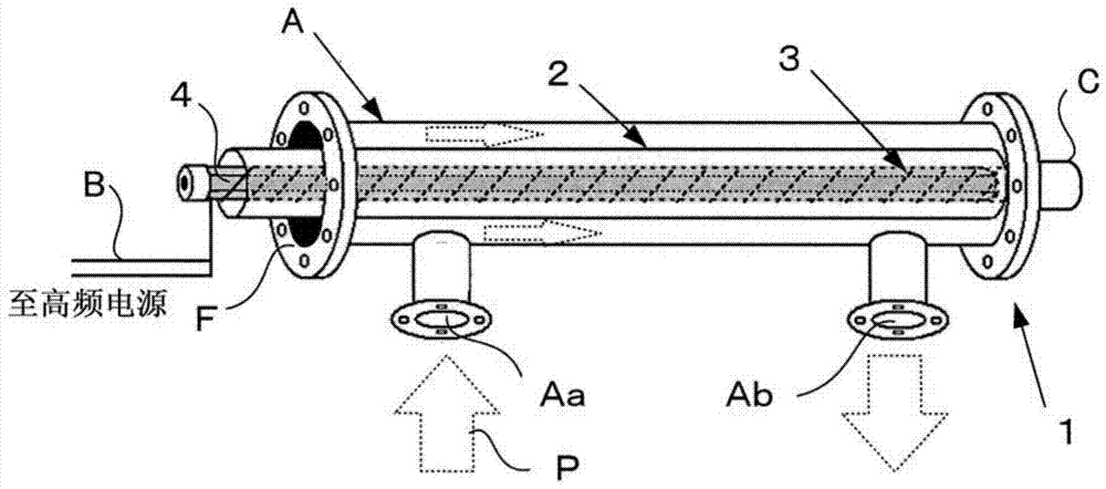
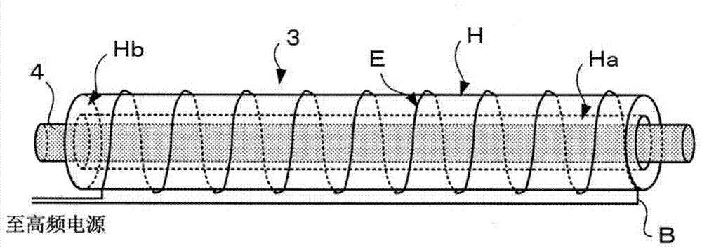
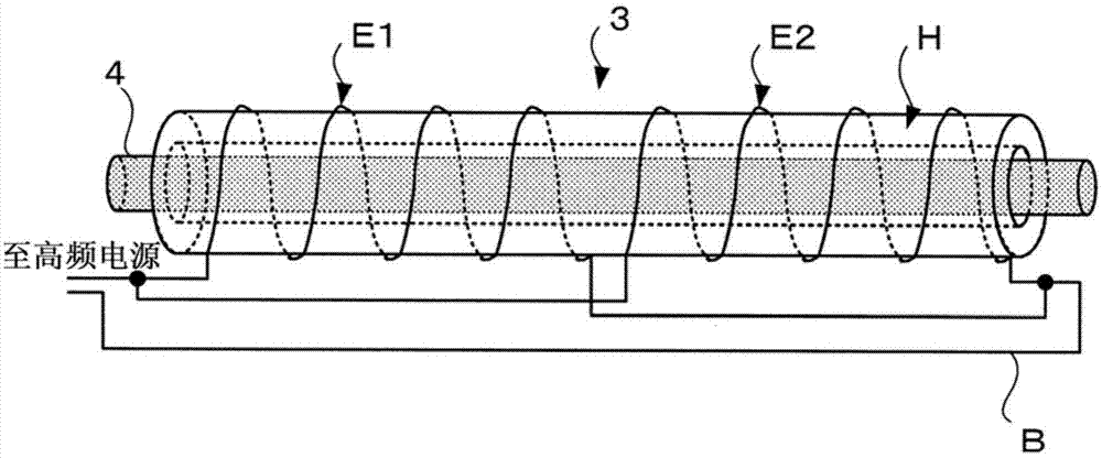
[0026] figure 1 It is a conceptual diagram showing an embodiment of the liquid processing device according to the present invention. figure 1 The shown liquid processing device 1 is of the following type: For example, in a cylindrical container A made of a material that is hard to corrode, such as stainless steel, the following figure 2 or image 3 The protective outer tube 2 of the shown electrodeless discharge ultraviolet irradiation device 3 uses the ultraviolet rays emitted from the electrodeless discharge ultraviolet irradiation device 3 to process the treatment liquid P passing between the cylindrical container A and the protective outer tube 2. deal with.

[0027]Both ends of the cylindrical container A are liquid-tightly sealed by the sealing portion F so that the processing liquid P does not leak to the outside, thereby forming the following flow ...


PUM


Abstract

A liquid processing apparatus has an ultraviolet ray discharge tube configured in a processing liquid flow path from an influx to an outflux of a processed liquid and used for irradiating ultraviolet rays of the processing liquid flowing past the flow path, the discharge tube has a hollow part penetrating through the interior thus to form a tube, a ferrite core is arranged at the hollow part, and one or more induction coils wraps the periphery of the discharge tube. Therefore, through applying higher voltage to the periphery of the discharge tube, discharge is easy to occur. Additionally, because the discharge space is disposed close to the surface of the discharge tube, the radiation quantity of vacuum ultraviolet rays for effectively resolving organic objects can be increased. Moreover, because a wide gap can be ensured between the ferrite core and the induction coils, stable and continuous discharge can easily occur. In addition, the ferrite core can be simply cooled, and thus the ultraviolet radiation efficiency is optimized.

Description

technical field [0001] The present invention relates to a liquid treatment device using an electrodeless discharge ultraviolet irradiation device that irradiates ultraviolet rays from an ultraviolet radiation discharge tube in response to high-frequency excitation of an induction coil. In particular, it relates to a technique for treating a liquid by efficiently and substantially uniformly generating a stable discharge with strong ultraviolet radiation over the entire length of a discharge tube. Background technique [0002] Conventionally, there is known a liquid treatment device that uses an ultraviolet radiation device for liquid treatment such as sterilization of liquid and oxidative decomposition of trace organic substances in the liquid or decomposition of refractory organic substances. In addition, there is a liquid processing device that uses an ultraviolet radiation device to remove a trace amount of organic matter in an ultrapure water production process that is in...

Claims


Application Information

Patent Timeline
IPC IPC(8): H01J65/04H01J61/52C02F1/32
CPCC02F1/32C02F2303/04H01J29/28H01J65/048H01J2235/1262
Inventor 井上昭浩清三·凯文·当间久保充正石井新
Owner PHOTOSCI JAPAN CORP
Why Eureka
Try Eureka