
Photoelectric conversion module

A photoelectric conversion module and photoelectric coupling technology, which is applied in the coupling of optical waveguides, etc., can solve the problems of difficult lens production, measurement and confirmation of optical path alignment components, and achieve the effect of reducing development time and cost and making production easy

Inactive Publication Date: 2016-12-21
HONG FU JIN PRECISION IND (SHENZHEN) CO LTD +1
View PDF6 Cites 0 Cited by
  • Summary
  • Abstract
  • Description
  • Claims
  • Application Information

AI Technical Summary

Problems solved by technology

This approach can effectively deflect the light and make the module smaller. However, on this structure, it is difficult to manufacture the lens, especially in the measurement and confirmation of the optical path alignment components.

Method used


Image

  • Photoelectric conversion module
  • Photoelectric conversion module
  • Photoelectric conversion module

Examples


Embodiment Construction

[0013] The present invention will be described in detail below in conjunction with the accompanying drawings.

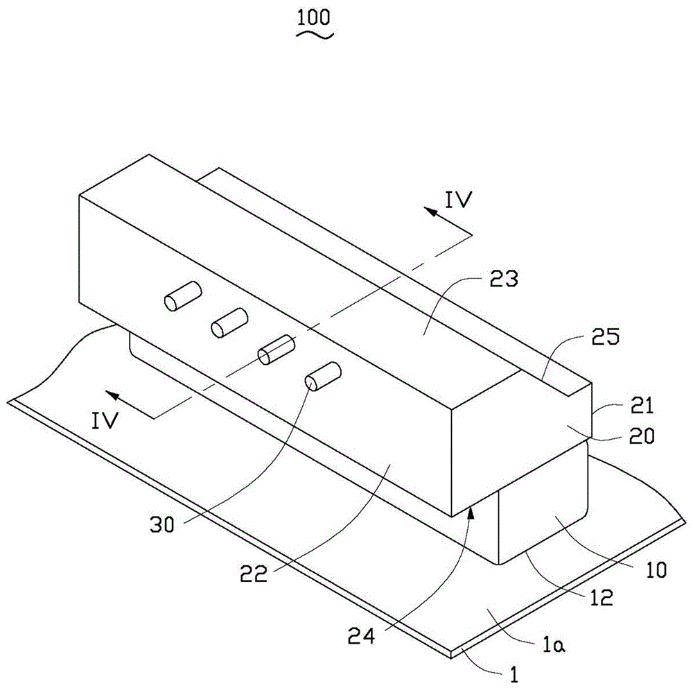
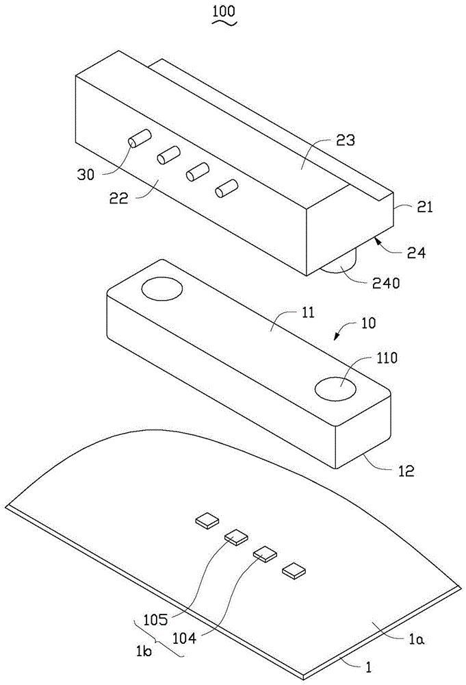
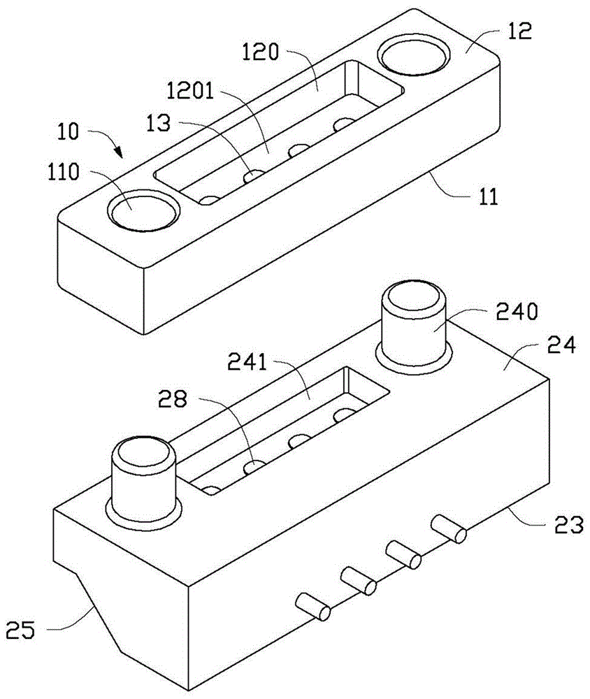
[0014] Please also refer to Figure 1 to Figure 4 , the photoelectric conversion module 100 provided by the embodiment of the present invention includes a circuit board 1 , a photoelectric coupler 10 , a jumper (Jumper) 20 and a plurality of optical fibers 30 . The photocoupler 10 is fixed on the circuit board 1 . The jumper 20 is detachably installed on the optical coupler 10 , and one end of each of the plurality of optical fibers 30 is installed in the jumper 20 .

[0015] The circuit board 1 includes a bearing surface 1a. Four photoelectric elements 1b are arranged on the carrying surface 1a. The photoelectric element 1 b includes two optical signal emitting elements 104 and two optical signal receiving elements 105 . The optical signal transmitting element 104 may be a laser diode (laser diode), and the optical signal receiving element 105 may be a photodiod...


PUM


Abstract

Provided is a photoelectric conversion module group which comprises a photoelectric coupling piece, a bridge-connecting device and multiple optical fibers. The photoelectric coupling piece can be detachably installed on the bridge-connecting device. The photoelectric coupling piece is provided with multiple first coupling lenses. The bridge-connecting device comprises a first external side surface, a second external side surface, a first end surface and a second end surface. The second external side surface extends towards the first external side surface so that multiple aligning holes are arranged, and the multiple optical fibers are respectively accommodated in the multiple aligning holes. The first end surface extends towards the first external side surface so that an inclined surface which is inclined is formed. One angle is formed by the first end surface and the inclined surface. The second end surface is also provided with a groove. The bottom part of the groove is provided with multiple second coupling lenses which are corresponding to the first coupling lenses. Each second coupling lens is arranged on an optical path which corresponds to the optical signal of the corresponding optical fiber and is reflected by the inclined surface. Each second coupling lens is correspondingly aligned with one first coupling lens. According to the photoelectric conversion module group, the optical path is easy to align.

Description

technical field [0001] The invention relates to a conversion module, in particular to a photoelectric conversion module. Background technique [0002] The photoelectric conversion module is used to connect the optical signal transmitting device and the optical fiber or between the optical fiber and the optical signal receiving device to realize the coupling of the optical signal and the mutual conversion between the optical signal and the electrical signal. Existing photoelectric conversion modules are used to bend the surface-emitting laser by 90 degrees to transmit energy to the optical fiber, or to bend the light transmitted by the optical fiber by 90 degrees to be received by the photodetector. The photoelectric conversion module is usually realized by using a lens made of high refractive index material with an angle of 45 degrees. This approach can effectively deflect the light and make the module smaller. However, in this structure, the lens is difficult to manufactur...

Claims


Application Information

Patent Timeline
Patent Type & Authority Patents(China)
IPC IPC(8): G02B6/43G02B6/42
Inventor 林奕村
Owner HONG FU JIN PRECISION IND (SHENZHEN) CO LTD
Learn More