Economic and efficient U-shaped electric lamp
A U-shaped, electric lamp technology, applied in the field of fluorescent lamps, can solve the problems of large occlusion surface of energy-saving lamps, affecting lighting efficiency, etc., and achieve the effects of simple structure, reduction of occlusion coefficient, and improvement of light output
Inactive Publication Date: 2014-05-07
ZHENGZHOU HANTONG ELECTRONICS TECH
View PDF0 Cites 0 Cited by
- Summary
- Abstract
- Description
- Claims
- Application Information
AI Technical Summary
Problems solved by technology
[0003] The purpose of the present invention is to provide an energy-saving and high-efficiency U-shaped electric lamp to solve the technical problem that the energy-saving lamp of the existing combination tube has a large shielding surface and affects the lighting efficiency
Method used
View moreImage
Smart ImageViewing Examples
Examples
Embodiment Construction
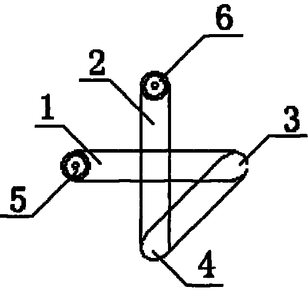
[0008] An energy-saving and high-efficiency U-shaped electric lamp, comprising an AU-shaped tube 1 and a BU-shaped tube 2, one end 3 of the A U-shaped tube 1 is connected to one end of the B U-shaped tube 2, and the A U-shaped tube 1 is connected to the BU-shaped tube 2. The type pipes 2 intersect to form an included angle.
Login to View More PUM
 Abstract
An economic and efficient U-shaped electric lamp comprises an AU tube and a BU tube, wherein one end of the AU tube is communicated with one end of the BU tube, and the AU tube and the BU tube are intersected to form an included angle. Furthermore, a range of the included angle is 90 degrees to 100 degrees, and 90 degrees is preferable. Two U-shaped tubes of the economic and efficient U-shaped electric lamp are bent and connected, and mutual blocking faces of the U-shaped tubes are decreased, but in the scheme, the light yield of the same U-shaped tubes is improved by about 12%, and the blocking coefficient is greatly reduced under the condition that the power is not changed. In addition, the economic and efficient U-shaped electric lamp has the advantages of being simple and attractive in structure and high in strength and efficiency.
Description
technical field [0001] The invention belongs to the technical field of fluorescent lamps, in particular to an energy-saving and high-efficiency U-shaped electric lamp with a small shielding surface. Background technique [0002] As a kind of high-efficiency energy-saving lamp, fluorescent lamp has gradually become the mainstream product of indoor lighting because of its advantages of energy saving. Existing energy-saving lamps have various forms such as single-tube and combination, but the illumination intensity of single-tube energy-saving lamps is not high, and the combination of multiple tubes will cause mutual shading, affecting the full use of light sources, and the lighting effect is not ideal. Form a complete discharge circuit. This multi-H-shaped annular fluorescent tube structure will cause the tubes to block each other, and the emitted light cannot be fully diffused, which will affect the lighting effect. Contents of the invention [0003] The object of the pre...
Claims
Login to View More Application Information
Patent Timeline
 Patent Type & Authority Applications(China)
IPC IPC(8): F21V17/00
Inventor 陈谦勇
Owner ZHENGZHOU HANTONG ELECTRONICS TECH
Features
- R&D
- Intellectual Property
- Life Sciences
- Materials
- Tech Scout
- Unparalleled Data Quality
- Higher Quality Content
- 60% Fewer Hallucinations
Learn More Browse by: Latest US Patents, China's latest patents, Technical Efficacy Thesaurus, Application Domain, Technology Topic, Popular Technical Reports.
© 2025 PatSnap. All rights reserved.Legal|Privacy policy|Modern Slavery Act Transparency Statement|Sitemap|About US| Contact US: help@patsnap.com

