
Intraoperative image correction for image-guided interventions

An image centering and correction system technology, applied in the field of image correction, can solve problems such as surgical navigation system errors

Inactive Publication Date: 2017-04-19
KONINKLJIJKE PHILIPS NV
View PDF4 Cites 0 Cited by
  • Summary
  • Abstract
  • Description
  • Claims
  • Application Information

AI Technical Summary

Problems solved by technology

This will introduce a large error to the overall surgical navigation system

Method used


Image

  • Intraoperative image correction for image-guided interventions
  • Intraoperative image correction for image-guided interventions
  • Intraoperative image correction for image-guided interventions

Examples


Embodiment Construction

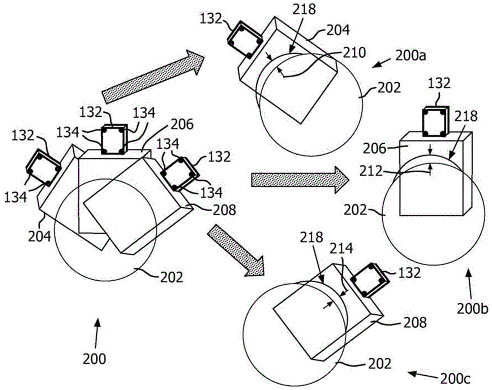
[0016] The principles of the present invention take into account differences in the velocity of sound waves traveling through a patient's anatomy. Experiments have shown that differences in the speed of sound consistently add 3-4% error in ultrasound (US) based navigation systems (eg 4mm error at a depth of 15cm). This embodiment corrects this error. The principles of the present invention reduce the overall error of the system when corrected using velocity modulation. In one instance, the error was significantly reduced from about 4 mm (at a depth of 15 cm) to about 1 mm.

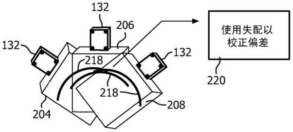
[0017] For ultrasound-based surgical navigation systems used for interventional procedures, real-time tracking of three-dimensional (3D) positions of US images is employed, along with information from the images, to correct for phase bias. This increases the accuracy of any US-guided interventional system.

[0018] It is to be understood that the present invention will be described in relation to medica...


PUM


Abstract

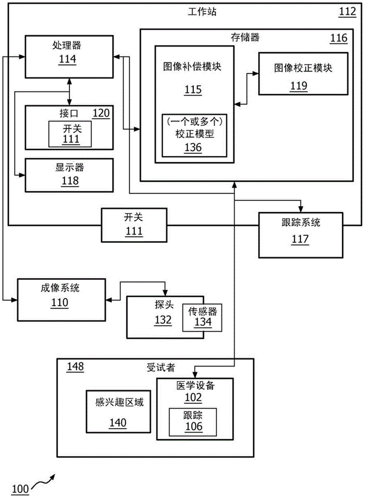
An imaging correction system includes a tracking imaging probe (132) configured to generate an imaging volume of a region of interest from different locations. The image compensation module (115) is configured to process image signals from a medical imaging device associated with the probe and compare one or more image volumes with a reference to determine a hypothetical wave velocity through the region of interest relative to A deviation between compensated wave velocities through the region of interest. An image correction module (119) is configured to receive the deviation determined by the image compensation module and generate a corrected image for display based on the compensated wave velocity.

Description

technical field [0001] The present disclosure relates to image correction, and more particularly to systems and methods for correcting accuracy errors in intraoperative images. Background technique [0002] Ultrasound (US) images are known to be distorted by discrepancies between assumed and actual sound velocities in different tissues. The US system assumes a substantially constant speed of sound. There are various methods that attempt to correct for this assumption. In doing so, most methods rely on US wave information returned from the anatomical features being imaged. Since a single US image does not include much inherent anatomical information, most of these methods fail to correct for bias due to the constant velocity assumption. [0003] In procedures where US images are used only for diagnostic purposes, phase deviation is not a serious problem. However, in US-guided interventions, the US images are closely related to externally tracked surgical tools. Typically...

Claims


Application Information

Patent Timeline
Patent Type & Authority Patents(China)
IPC IPC(8): G01S7/52G01S15/89
CPCG01S7/52049G01S15/899G01S15/8936A61B8/4254G06T5/70
Inventor C·S·霍尔A·K·贾殷
Owner KONINKLJIJKE PHILIPS NV
Learn More