
The connecting structure connecting corner codes and skeleton beams

A technology for connecting structures and connecting angles, which is applied in the direction of building components, building structures, walls, etc., and can solve the problem of no freedom of horizontal and vertical movement on the top hanging side, the constraints of horizontal and vertical expansion and contraction of metal plates, and the drum surface and concave surface of the plate surface. The situation cannot be effectively improved and other problems, to achieve the effect of correct interface, reliable connection, and prevention of drum surface and concave surface

Active Publication Date: 2015-12-30
苏州市鑫泰建筑装璜有限公司
View PDF5 Cites 0 Cited by
  • Summary
  • Abstract
  • Description
  • Claims
  • Application Information

AI Technical Summary

Problems solved by technology

However, since the self-weight load of the entire metal plate needs to be borne by the top flange (hanging edge) of the metal plate, the top hanging edge can only be fastened to the frame beam by connecting the corner brackets, resulting in no horizontal and vertical movement freedom for the top hanging edge
Therefore, the horizontal and vertical expansion and contraction space of the metal plate is severely restricted, and the situation of drum and concave surface on the plate surface cannot be effectively improved

Method used


Image

  • The connecting structure connecting corner codes and skeleton beams
  • The connecting structure connecting corner codes and skeleton beams

Examples


Embodiment Construction

[0020] The specific implementation manners of the present invention will be further described below in conjunction with the drawings and examples. The following examples are only used to illustrate the technical solution of the present invention more clearly, but not to limit the protection scope of the present invention.

[0021] The technical scheme of concrete implementation of the present invention is:

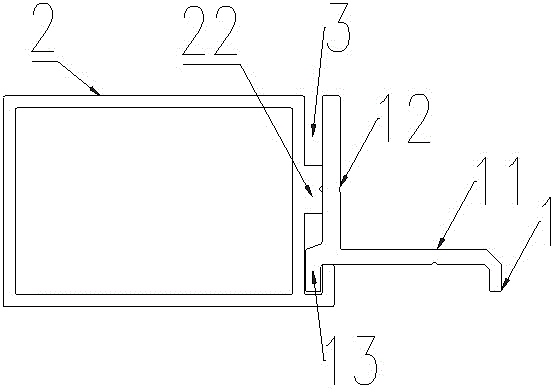
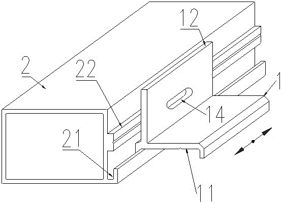
[0022] Such as figure 1 , figure 2 As shown, a connection structure connecting the corner code 1 and the skeleton beam 2,

[0023] The connecting corner bracket 1 is provided with a flat support side 11 for supporting the hanging side of the metal plate, a vertical side 12 opposite to the outer vertical surface of the skeleton beam 2, and a hook side 13 for hanging on the skeleton beam 2 , the vertical side 12 is provided with a flat elongated hole 14;

[0024] The outer vertical surface of the skeleton crossbeam 2 is provided with a hook groove 21 for connecting the ...


PUM


Abstract

The invention discloses a connecting structure for a connecting corner and a framework crossbeam. The connecting corner is provided with a horizontal supporting edge used for supporting a metal plate hanging edge, a vertical edge opposite to an outer vertical surface of the framework crossbeam and a hook edge used for being hooked on the framework crossbeam; a horizontal elongated hole is formed in the vertical edge. The outer vertical surface of the framework crossbeam is provided with a hook groove allowing the hook edge of the connecting corner to be hooked and a cross convex rib allowing the vertical edge of the connecting corner to cling to. The hook edge of the connecting corner is hooked in the hook groove of the framework crossbeam, the vertical edge of the connecting corner is screwed by a screw to cling to the cross convex rib of the framework crossbeam, the screw penetrates the elongated hole of the vertical edge, and a cross sliding clearance is formed between the hook groove and the hook edge. By the connecting structure, the connecting corner and the framework crossbeam form a cross sliding pair.

Description

technical field [0001] The invention relates to a connecting structure connecting corner brackets and skeleton beams, which is applied to metal curtain walls. Background technique [0002] The metal curtain wall material has high strength, light material, and convenient coloring treatment; the surface has been formed, and the grid limit is small, and it is easy to realize large grids and overall corner processing; it is easy to process and easy to realize the advantages of mass production. Therefore, the metal curtain wall has been favored by architects at home and abroad, and has a wide market application. [0003] However, the temperature change performance of the metal curtain wall material is relatively sensitive. In daily temperature changes, the surface of the metal curtain wall will appear uneven, and its flatness will also change with the change of temperature. Therefore, the flatness problem of metal curtain wall has become the most difficult quality common problem...

Claims


Application Information

Patent Timeline
Patent Type & Authority Patents(China)
IPC IPC(8): E04B2/88
Inventor 居云峰浦永男李青
Owner 苏州市鑫泰建筑装璜有限公司
Learn More