Transmission mechanism with multiple chute inclined surfaces

A technology of transmission mechanism and chute, which is applied in the field of multi-chute inclined-plane transmission mechanism, which can solve the problems that the transmission mechanism cannot be adapted, and the stepped cylindrical or tapered workpiece cannot be oriented to transmit, etc.

Inactive Publication Date: 2014-04-30
CHONGQING MING SHIELD ELECTROMAGNETIC VALVE
View PDF0 Cites 0 Cited by
  • Summary
  • Abstract
  • Description
  • Claims
  • Application Information

AI Technical Summary

Problems solved by technology

[0004] The technical problem to be solved by the present invention is that in the prior art, the stepped cylindrical or conical workpieces cannot be transported in a certain direction, and the transmission mechanism cannot adapt to the shortcomings of workpieces of different sizes.

Method used


Image

  • Transmission mechanism with multiple chute inclined surfaces
  • Transmission mechanism with multiple chute inclined surfaces

Examples


Embodiment Construction

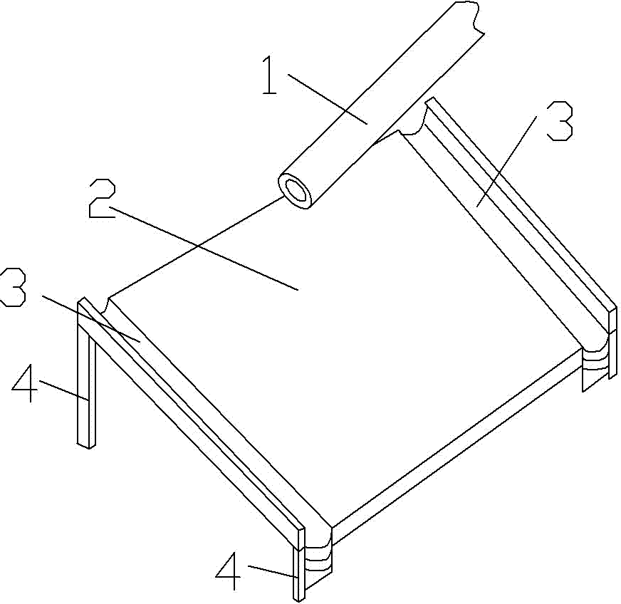
[0011] The reference signs in the accompanying drawings of the description include: feeding chute 1 , inclined plate 2 , conveying chute 3 , and support rod 4 .

[0012] Below in conjunction with accompanying drawing and embodiment technical solution of the present invention is described in further detail:

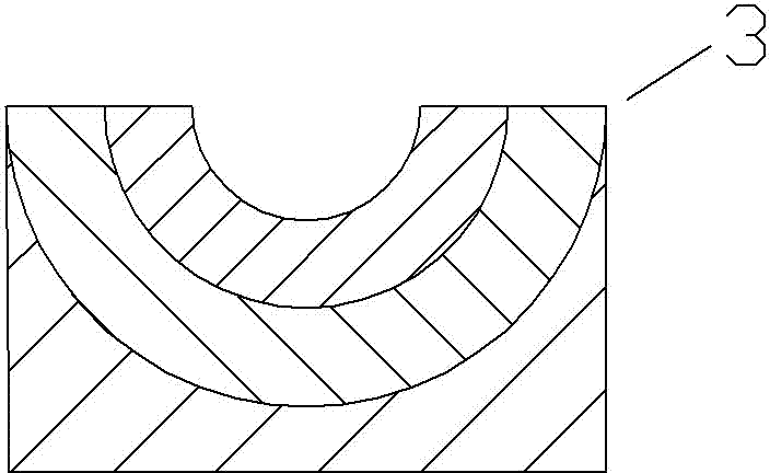
[0013] Such as figure 1 , figure 2 As shown, a multi-chute inclined-plane transmission mechanism includes a feeding chute 1 and an inclined flat plate 2, the feeding chute 1 is arranged on the top of the inclined flat plate 2, and a transmission chute 3 is respectively arranged on both sides of the inclined flat plate 2, and the inclined flat plate 2 The direction of inclination is perpendicular to the feeding axis of the feed chute 1. The transfer chute 3 includes three stacked grooves with different radii. The radii of the three grooves are 1mm, 2mm, and 3mm in sequence. There are through holes, the positions of the through holes of the three stacked grooves coincide,...


PUM


Abstract

The invention discloses a transportation device, and particularly relates to a transmission mechanism with multiple chute inclined surfaces. The transmission mechanism comprises a feeding chute and an inclined flat plate, the feeding chute is formed in the top end of the inclined flat plate, transmission chutes are formed in two sides of the inclined flat plate, the inclined direction of the inclined flat plate is perpendicular to a feeding axis of the feeding chute, the transmission chutes comprise a plurality of stacked grooves with different radiuses. The transmission mechanism is simple in structure, and different sizes of stepped cylindrical or conical workpieces can be transmitted in an oriented manner.

Description

technical field [0001] The invention relates to a transportation device, in particular to a multi-chute inclined-plane transmission mechanism. Background technique [0002] In ancient China, people began to overturn carts to carry water. By the middle of the 17th century, rack conveying equipment began to be used; in the middle of the 19th century, various modern structure conveying equipment were developed and produced one after another, such as the steel belt conveyor in Switzerland, the inertial conveyor in Britain and Germany, etc. Since then, the conveyor has been continuously improved under the influence of technological progress in machinery manufacturing, electrical machinery, chemical industry and metallurgical industry. An indispensable part of the mechanization and automation of the handling system. [0003] During factory production and processing, stepped cylindrical or conical workpieces cannot be conveyed in a directional manner, and need to be placed manual...

Claims


Application Information

Patent Timeline
Patent Type & Authority Applications(China)
IPC IPC(8): B65G11/00
Inventor 姜静慧
Owner CHONGQING MING SHIELD ELECTROMAGNETIC VALVE
Why Eureka
Try Eureka