Rotating flowerpot
A flowerpot and rotating motor technology, applied in the field of horticulture, to ensure the effect of thriving growth
- Summary
- Abstract
- Description
- Claims
- Application Information
AI Technical Summary
Problems solved by technology
Method used
Image
Examples
Embodiment 1
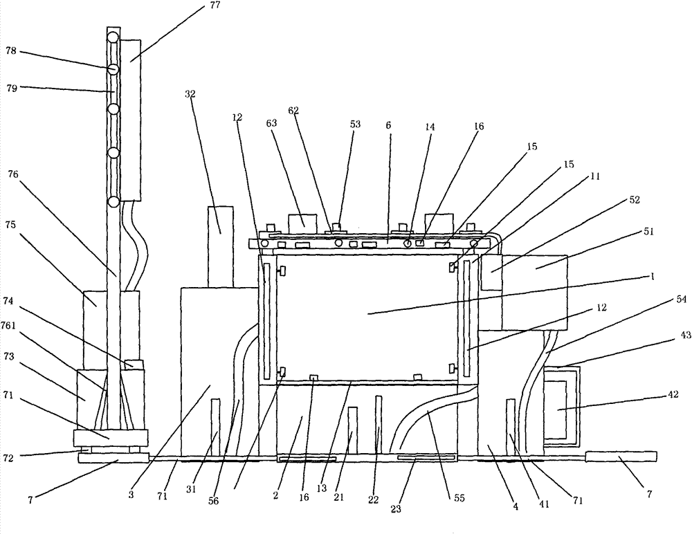
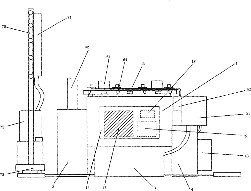
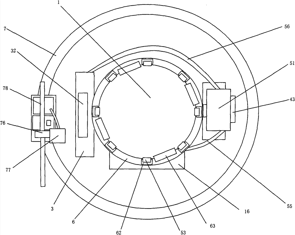
[0025] Example 1: Such as figure 1 , figure 2 with image 3 As shown, a flowerpot includes a pot body 1, and the pot body 1 is circular. A rectangular protrusion 16 is provided on the basin 1, and a display screen 17 is provided on the rectangular protrusion 16, and the display screen 17 is a touch screen. A single chip microcomputer 19 and a signal generator 18 are arranged inside the rectangular bump 16, and the single chip microcomputer 19 controls the signal generator 18. A cavity 11 is provided between the outer side wall of the basin 1 and the inner side wall of the basin 1, and a number of heating resistance wires 12 are arranged in the cavity 11. The heating resistance wires 12 can be evenly distributed in the cavity 11, and It can be continuously arranged in the cavity 11, and the heating resistance wire 12 is controlled by the single chip microcomputer 19. A collecting tank 2 is arranged at the bottom of the basin 1, a permeable plate 13 is arranged between the basi...
Embodiment 2
[0031] Example 2: Such as Figure 4 , Figure 5 with Image 6 As shown, a flowerpot includes a pot body 1, and the pot body 1 is circular. A rectangular protrusion 16 is provided on the basin 1, and a display screen 17 is provided on the rectangular protrusion 16, and the display screen 17 is a touch screen. A single chip microcomputer 19 and a signal generator 18 are arranged inside the rectangular bump 16, and the single chip microcomputer 19 controls the signal generator 18. A cavity 11 is provided between the outer side wall of the basin 1 and the inner side wall of the basin 1, and the cavity 11 is provided with a number of electromagnets 82. The electromagnets 82 are elongated, and the electromagnets 82 are vertically placed in the cavity 11 , And evenly distributed circumferentially in the cavity 11. A number of magnets 81 are arranged in the basin body 1, and the magnets 81 can be mixed in the soil. The magnets 81 have no arrangement rules in the soil and can be placed...
Embodiment 3
[0035] Example 3: Such as Figure 7 , Figure 8 with Picture 9 As shown, a flowerpot includes a pot body 1, and the pot body 1 is circular. A rectangular protrusion 16 is provided on the basin 1, and a display screen 17 is provided on the rectangular protrusion 16, and the display screen 17 is a touch screen. A single chip microcomputer 19 and a signal generator 18 are arranged inside the rectangular bump 16, and the single chip microcomputer 19 controls the signal generator 18. A cavity 11 is provided between the outer side wall of the basin 1 and the inner side wall of the basin 1. The upper end of the cavity 11 is provided with a number of air outlets 124, and the lower end is provided with a number of air inlets 121. The air outlets 124 and the air inlets 121 are uniform The circumference is arranged in the cavity 11. A plurality of suction fans 122 are arranged above the suction opening 121, and the suction fans 122 and the suction openings 121 are evenly distributed in...
PUM
 Abstract
Description
Claims
Application Information
 - R&D
- Intellectual Property
- Life Sciences
- Materials
- Tech Scout
- Unparalleled Data Quality
- Higher Quality Content
- 60% Fewer Hallucinations
Browse by: Latest US Patents, China's latest patents, Technical Efficacy Thesaurus, Application Domain, Technology Topic, Popular Technical Reports.
© 2025 PatSnap. All rights reserved.Legal|Privacy policy|Modern Slavery Act Transparency Statement|Sitemap|About US| Contact US: help@patsnap.com


