Ventilating system of heavy current circuit-breaker equipment

A technology of ventilation system and circuit breaker, applied in the field of ventilation system, can solve the problems of increasing the heat of the busbar, economic loss, equipment impact, etc., and achieve the effect of reducing the contact area, ensuring the use environment, and prolonging the life of the equipment

Inactive Publication Date: 2014-04-23
ZHONGSHAN MINGYANG ELECTRIC
View PDF5 Cites 1 Cited by
  • Summary
  • Abstract
  • Description
  • Claims
  • Application Information

AI Technical Summary

Problems solved by technology

[0002] In the current market, with the increase of electrical equipment, in the low-voltage power supply system, the demand for high-current products is increasing. Under normal circumstances, the rated current of 4000A and above can be defined as high-current, which is for low-voltage switches. The cabinet puts forward high protection requirements. This type of cabinet is a product with high airtightness, and the design requirements for the protection level are relatively high, basically above IP42. The calorific value of the current low-voltage circuit breaker, part of the heat generated by it is dissipated to the space through the conductor connected to it, which increases the heat of the busbar. When the temperature of the main busbar and busbar rises, the carrying capacity increases with the temperature. If the busbar device is in the power distribution cabinet, its rated current will decrease due to the change of heat dissipation conditions, which will easily cause overload, affect the equipment, and bring economic losses.

Method used


Image

  • Ventilating system of heavy current circuit-breaker equipment
  • Ventilating system of heavy current circuit-breaker equipment
  • Ventilating system of heavy current circuit-breaker equipment

Examples


Embodiment Construction

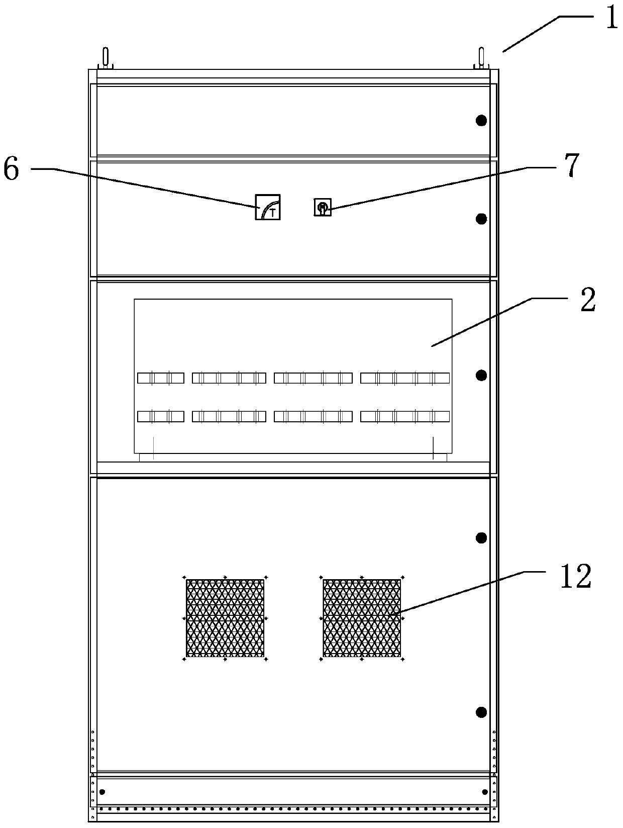
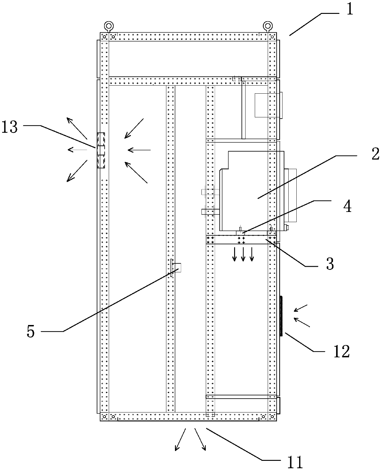
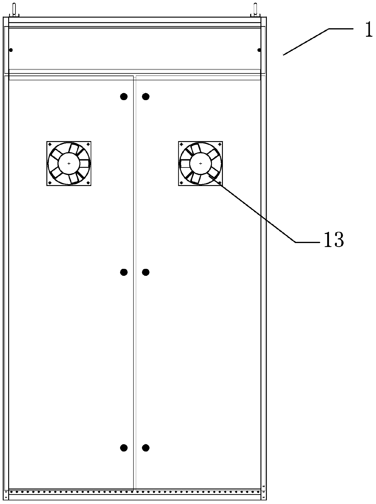
[0020] refer to Figure 1 to Figure 5 , Figure 1 to Figure 5 It is a structural schematic diagram of a specific embodiment of the present invention. As shown in the figure, the ventilation system of the high-current circuit breaker equipment includes a large-current circuit breaker 2 and a cabinet 1 for installing the circuit breaker 2. The circuit breaker 2 It is installed and fixed in the cabinet body 1 through an installation base plate 3, and several pads 4 are arranged between the circuit breaker 2 and the installation base plate 3, and the circuit breaker 2 is raised by the pads 4 to reduce the overall force-bearing contact area , the installation bottom plate 3 is provided with a number of cooling slots, when the components are running, the heat generated by the components can be quickly conducted out of the cabinet body 1 through the cooling slots.

[0021] As shown in the figure, the cabinet body 1 is provided with a plurality of ventilation holes 11, air inlet hole...


PUM


Abstract

The invention discloses a ventilating system of heavy current circuit-breaker equipment. The ventilating system comprises a heavy current circuit-breaker and a cabinet for accommodating the heavy current circuit-breaker, wherein the circuit-breaker is mounted fixedly in the cabinet through a mounting plate; a plurality of cushion and supporting blocks are arranged between the circuit-breaker and the mounting plate; the mounting plate is provided with a plurality of radiating slot holes; the circuit-breaker is lifted by the cushion and supporting blocks, and the integral stressed contact area is reduced; when an element works, heat generated by the element can be quickly transferred out of the cabinet through the radiating slot holes, and a plurality of vent holes and air inlet holes and a fan are configured in the cabinet to form radiating channels, so that the heat in the cabinet can be quickly discharged, the operating environment of devices in the cabinet is effectively guaranteed, and the service life of the equipment is prolonged.

Description

technical field [0001] The invention relates to a ventilation system for large current circuit breaker equipment. Background technique [0002] In the current market, with the increase of electrical equipment, in the low-voltage power supply system, the demand for high-current products is increasing. Under normal circumstances, the rated current of 4000A and above can be defined as high-current, which is for low-voltage switches. The cabinet puts forward high protection requirements. This type of cabinet is a product with high airtightness, and the design requirements for the protection level are relatively high, basically above IP42. The calorific value of the current low-voltage circuit breaker, part of the heat generated by it is dissipated to the space through the conductor connected to it, which increases the heat of the busbar. When the temperature of the main busbar and busbar rises, the carrying capacity increases with the temperature. And lower, the busbar device i...

Claims


Application Information

Patent Timeline
Patent Type & Authority Applications(China)
IPC IPC(8): H02B1/56
Inventor 聂菲菲彭哲王秋菊温建仁于冬初
Owner ZHONGSHAN MINGYANG ELECTRIC
Why Eureka
Try Eureka