
A kind of sediment solution sampling device and sampling method

A sampling device and solution technology, applied to the sampling device and other directions, can solve the problems such as the size and shape of the sampler are not optimized, the sampling method is unreasonable, and the water flow interference, etc. Effect

Active Publication Date: 2016-01-20
HOHAI UNIV
View PDF4 Cites 0 Cited by
  • Summary
  • Abstract
  • Description
  • Claims
  • Application Information

AI Technical Summary

Problems solved by technology

Therefore, when studying the problem of suspended matter in a sand-carrying water flow, it is necessary to use the sampling method to accurately measure the sediment concentration. Since the sampler is directly in contact with the water flow, it will inevitably interfere with the water flow, thereby causing measurement errors. The traditional sampler The size and shape are not optimized, and the sampling method is not necessarily unreasonable, resulting in larger errors

Method used


Image

  • A kind of sediment solution sampling device and sampling method
  • A kind of sediment solution sampling device and sampling method
  • A kind of sediment solution sampling device and sampling method

Examples


Embodiment 1

[0027] The sediment concentration is measured in the laboratory glass tank, the tank is 12m long, 0.42m wide, and 0.7m high, and a constant and uniform sand-carrying water flow with a water depth of 18cm and a stable concentration is formed in the tank. The concentration of sediment in the direction of water depth is different. When the turbulent characteristics of water flow are different, the distribution pattern of sediment concentration will be different. When the water flow is a turbulent flow in an ordinary open channel with a smooth bed surface (the distribution law of the average flow velocity of the water flow is as follows Figure 4 shown), the sediment concentration measurement results are as follows Figure 5 shown. It can be seen that the sediment concentration is in the reverse S-shaped distribution form in the vertical direction, which is consistent with the theoretical distribution form. The distribution of the sediment concentration can be calculated by using...

Embodiment 2

[0029] To change the water flow conditions and the average concentration of sediment in the laboratory tank, the specific method can be to arrange rigid cylinders with strong water resistance on the bed surface, increase the roughness of the tank bed surface, and form a stable water depth of 18cm in the tank. Concentrated sand-carrying water flow. Similarly, the concentration of sediment in the direction of water depth is different, and the measurement results of sediment concentration are as follows: Figure 6 As shown, it can be seen that the sediment concentration is in a hyperbolic upward concave distribution form in the vertical direction, which is caused by the large roughness of the bed surface and the difference in the turbulent characteristics of the water flow in the tank from the smooth side wall. In this case, the traditional The rouse formula of the sediment concentration distribution cannot be calculated, and other suitable methods need to be sought. By comparin...


PUM

PropertyMeasurementUnit
The inside diameter ofaaaaaaaaaa

Abstract

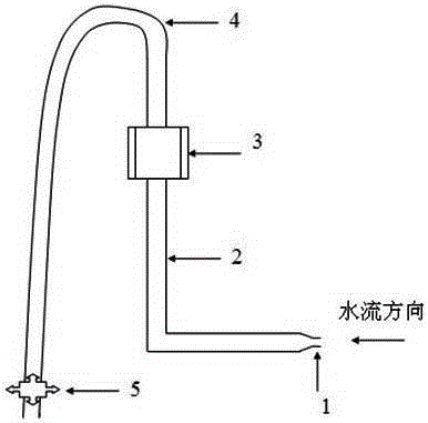
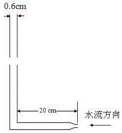
The invention discloses a sediment solution sampling device and a sampling method. The device comprises a water inlet (1), an L-shaped round tube (2), a fixing device (3), a rubber tube (4) and a rubber tube installed at the outlet of the rubber tube. Control valve (5); the horizontal port of the L-shaped round pipe (2) is connected to the water inlet (1), and the vertical port is connected to the rubber tube (4); the vertical part of the L-shaped round pipe (2) Fixed on the fixture (3) and able to move up and down. The method of the present invention is to direct the horizontal part of the L-shaped round pipe (2) to the direction of the incoming flow, make the water inlet (1) reach the position of the sampling point through the fixing device (3), and adjust the control valve (5) to ensure that the water inlet (1) The flow rate is consistent with the surrounding water flow rate, and the sediment solution sampling is completed accurately. The invention can reduce the interference to the water flow, significantly improve the measurement accuracy of the sediment concentration, and has great significance for the research on the problem of suspended matter in the sand-laden water flow.

Description

technical field [0001] The invention relates to a sediment solution sampling device and a sampling method, belonging to the technical field of water flow measurement. Background technique [0002] The measurement of sediment concentration is an important content in the observation of hydrological elements and the study of sediment-carrying water flow, and it is indispensable for the study of the calculation of sediment load and the distribution of vertical lines of suspended sediment. The measurement methods of sediment concentration can be generally divided into sampling method and non-sampling method. Although the sampling method is not efficient, it can guarantee high measurement accuracy. Non-sampling methods such as vibration method, photoelectric method, ray method, ultrasonic method, and laser method may be more efficient, but affected by various factors such as sediment particles and water flow characteristics, the measurement accuracy is difficult to guarantee, and ...

Claims


Application Information

Patent Timeline
IPC IPC(8): G01N1/10
Inventor 吕升奇唐洪武陈红袁礼伟郭美娇白雪冰
Owner HOHAI UNIV
Learn More