
Laser cutting machine with up and down exhaust system

A laser cutting machine and cutting head technology, applied in laser welding equipment, manufacturing tools, welding equipment, etc., can solve the problems of smoke and dust dissipation, time-consuming and labor-intensive problems

Active Publication Date: 2014-04-23
GUANGDONG HANS YUEMING LASER GRP CO LTD
View PDF6 Cites 3 Cited by
  • Summary
  • Abstract
  • Description
  • Claims
  • Application Information

AI Technical Summary

Problems solved by technology

[0003] The traditional exhaust system can extract most of the smoke and dust generated during the cutting process, but a considerable part of the smoke and dust escapes to the surrounding environment and adheres to the surface of the cut material
Therefore, in industries that require high cleanliness on the surface of the cutting workpiece, such as the light guide plate industry, the traditional smoke extraction system of the laser cutting machine cannot meet the requirements at all, because the smoke generated during the cutting process adheres to the surface of the material being cut. , it is often necessary to remove the dust attached to the cut material, which is time-consuming and laborious

Method used


Image

  • Laser cutting machine with up and down exhaust system
  • Laser cutting machine with up and down exhaust system
  • Laser cutting machine with up and down exhaust system

Examples


Embodiment Construction

[0016] In order to make the technical solution of the present invention more clearly expressed, the present invention will be further described below in conjunction with the accompanying drawings.

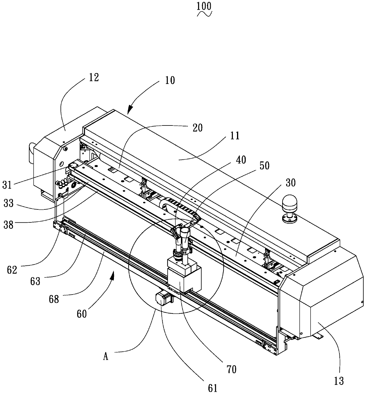
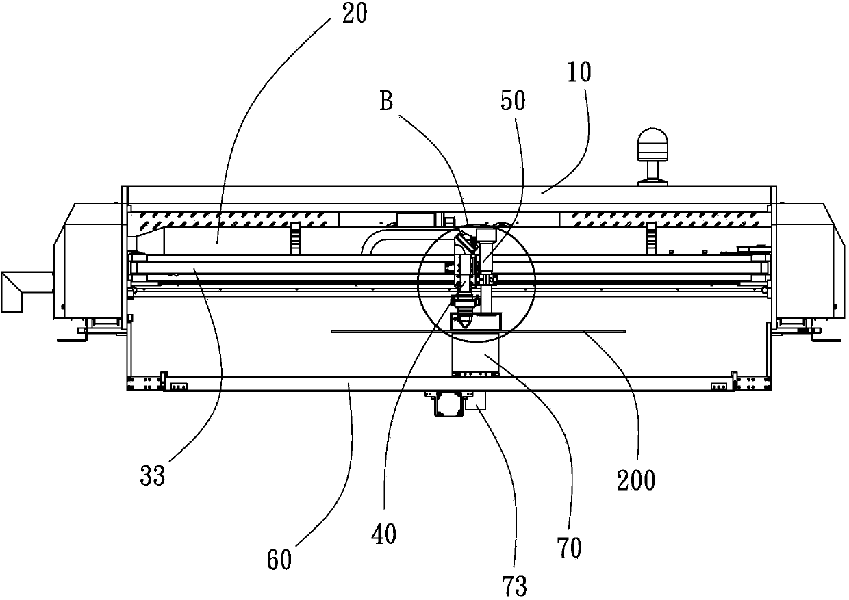
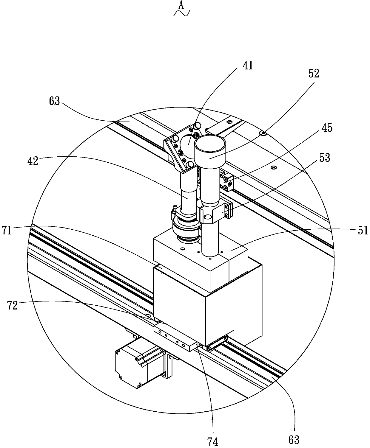
[0017] like Figure 1 to Figure 4 Shown is a laser cutting machine 100 with a vertical pumping system according to a preferred embodiment of the present invention, which is used to cut a flat plate-shaped material 200 to be cut. This laser cutting machine 100 with up and down pumping system includes a frame 10, a laser tube 20 installed in the frame 10, a first moving device 30 arranged on the top of the frame 10, connected with the first moving device 30 The cutting device 40 , the upper draft device 50 connected to the cutting device 40 , the second moving device 60 arranged at the bottom of the frame 10 , and the lower draft device 70 installed on the second moving device 60 . The material to be cut 200 is placed between the upper draft device 50 and the lower draft device 70, ...


PUM


Abstract

A laser cutting machine with an up and down exhaust system comprises a machine frame, a laser tube, a first movement device, a cutting device, an upper exhaust device, a second movement device and a lower exhaust device; the cutting device comprises a cutting head; the upper exhaust device comprises an upper cover, an exhaust tube and a fixing part which is connected with the exhaust tube and the cutting device; the upper cover covers the cutting head; the bottom surface of the upper cover is provided with the opening so as to face the top surface which covers materials to be cut; the lower exhaust device comprises the suction opening, the locking portion and the air outlet; the suction opening is formed at the top of the lower exhaust device; the locking portion is arranged on one side of the bottom of the lower exhaust device; the air outlet is formed in the other side of the bottom of the lower exhaust device; the suction opening faces the bottom surface which covers the materials to be cut; the locking portion is connected with the second movement device; the synchronous movement of the lower exhaust device, the cutting head and the upper cover is driven by the second movement device. According to the laser cutting machine with the up and down exhaust system, the laser cutting machine and the cutting device move synchronously through the upper exhaust device and the lower exhaust device and accordingly the smoke which is cut out through the materials to be cut is sucked up and down simultaneously and accordingly the clean and safe effect can be achieved.

Description

technical field [0001] The invention relates to a laser cutting device, in particular to a laser cutting machine with an up-and-down pumping system of a follow-up type and an up-and-down pumping system. Background technique [0002] Laser cutting machines work on the principle of laser ablation of materials, so smoke and dust will inevitably be generated during the cutting process. The smoke and dust generated during the cutting process will spread to the surrounding environment on the one hand, which is not conducive to the health of the operator itself, and on the other hand, it will adhere to the surface of the cut material and cause pollution. [0003] The traditional exhaust system can extract most of the smoke and dust generated during the cutting process, but a considerable part of the smoke and dust escapes to the surrounding environment and adheres to the surface of the cut material. Therefore, in industries that require high cleanliness on the surface of the cutti...

Claims


Application Information

Patent Timeline
Patent Type & Authority Applications(China)
IPC IPC(8): B23K26/38B23K26/142B23K26/08
CPCB23K26/142B23K26/361
Inventor 黄龙杰郑其锋王军
Owner GUANGDONG HANS YUEMING LASER GRP CO LTD
Learn More