
Electrode plate automatic cleaning machine

An electrode plate, automatic technology, applied in the direction of removing smoke and dust, cleaning methods and utensils, cleaning methods using tools, etc., can solve problems such as low work efficiency, endangering life and health, affecting electroplating efficiency, etc., to achieve easy replacement and personal safety. Effect

Active Publication Date: 2016-05-18
上海科德轧辊表面处理有限公司
View PDF8 Cites 0 Cited by
  • Summary
  • Abstract
  • Description
  • Claims
  • Application Information

AI Technical Summary

Problems solved by technology

[0002] In the process of repairing the roll by electroplating, electrode plates are needed, but after long-term use, debris will accumulate on the surface of the electrode plates, which will affect the efficiency of electroplating
The current method of dealing with impurities on the surface of the electrode plate is to manually use an angle grinder to grind the surface of the electrode plate to achieve the purpose of removing impurities from the surface of the electrode plate. However, this method of removing impurities is inefficient and the angle grinder is grinding A large amount of dust will be generated during the process, and the inhalation of dust by the staff will endanger life and health

Method used


Image

  • Electrode plate automatic cleaning machine
  • Electrode plate automatic cleaning machine
  • Electrode plate automatic cleaning machine

Examples


Embodiment Construction

[0036] In order to make the technical means, creative features, objectives and effects achieved by the present invention easy to understand, the present invention will be further described below in conjunction with specific illustrations.

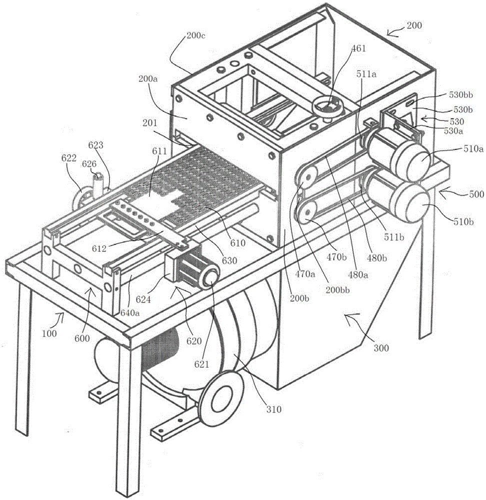
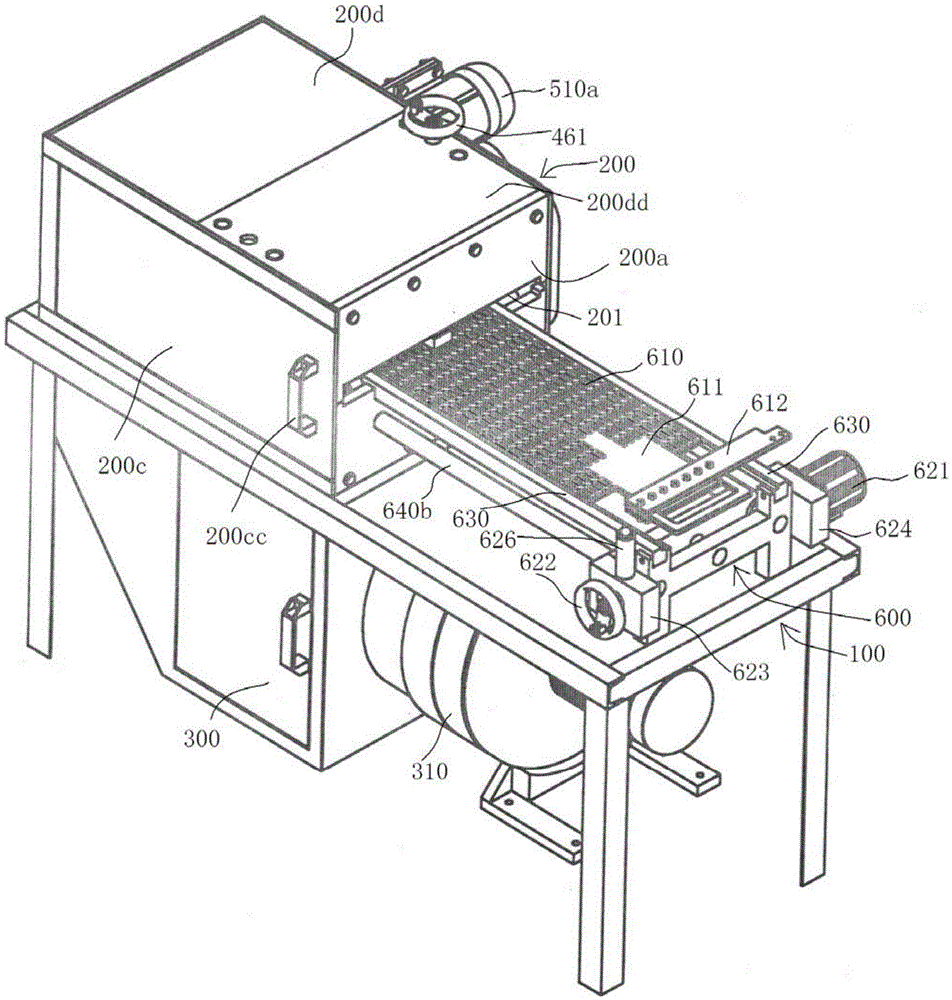
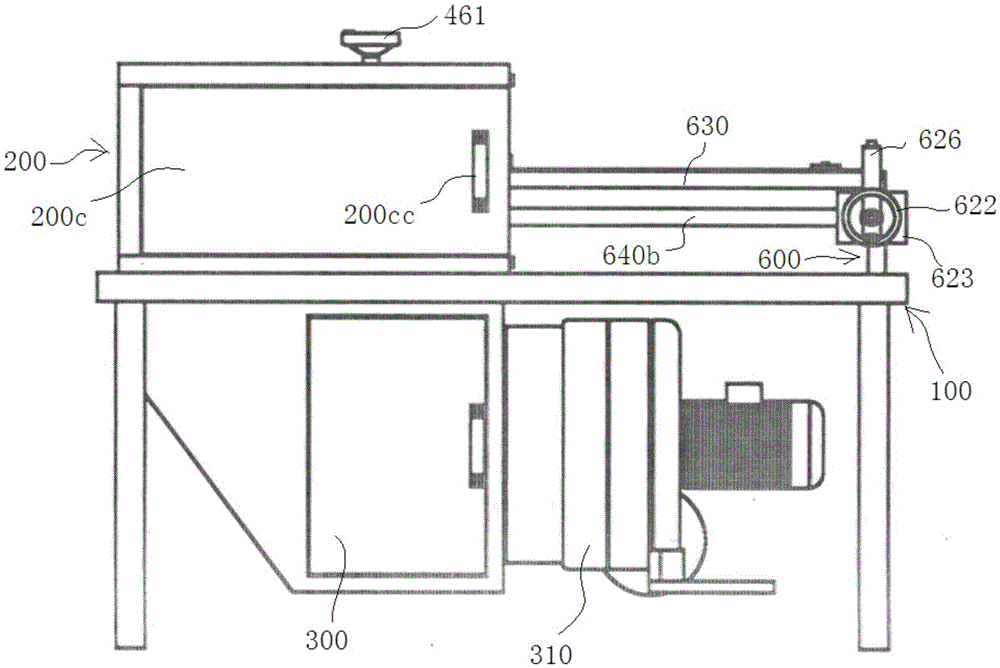
[0037] see Figure 1 to Figure 7As shown, the electrode plate automatic impurity removal machine includes a frame 100, and an impurity removal chamber 200 is arranged on the upper end of the tail end of the frame 100, and a dust recovery chamber 300 is arranged on the lower part of the tail end of the frame 100, and the dust recovery chamber 300 is connected with the impurity removal chamber. The room 200 is connected, and the dust recovery room 300 is also connected with an exhaust fan 310. The impurity removal room 200 will generate dust during the working process, and the exhaust fan 310 will form a negative pressure in the dust recovery room 300, and the dust will be absorbed into the dust recovery room. Within 300, it is guaranteed tha...


PUM


Abstract

The invention discloses an electrode plate automatic impurity removing machine which comprises a machine frame, an impurity removing chamber arranged at the first end of the machine frame, a dust recycling chamber arranged on the lower portion of the first end of the machine frame and communicated with the impurity removing chamber, an impurity removing device arranged in the impurity removing chamber at the position close to an electrode plate inlet / outlet, a driving device arranged on the second chamber wall of the impurity removing chamber adjacent to the first chamber wall and used for driving the impurity removing device to remove impurity for electrode plates passing through an impurity removing channel, a pair of feeding tracks and a feeding mechanism arranged on the feeding tracks in a sliding mode and used for delivering the electrode plates needing impurity removing into the impurity removing channel through the electrode plate inlet / outlet to conduct impurity removing. The electrode plate inlet / outlet is arranged in the first chamber wall of the impurity removing chamber facing the second end of the machine frame. The dust recycling chamber is connected with an air extracting device. Two ends of the pair of feeding tracks are arranged on the machine frame through sliding track supports. The machine achieves automatic impurity removing on the electrode plates, dust is not leaked in the impurity removing process, and the machine can adapt to impurity removing of electrode plates with different thicknesses, and the impurity removing device is convenient to replace.

Description

technical field [0001] The invention relates to the technical field of electrode plates for electroplating, in particular to an automatic impurity remover for electrode plates for electroplating. Background technique [0002] In the process of repairing the roll by electroplating, electrode plates are needed, but after long-term use, debris will accumulate on the surface of the electrode plates, which will affect the efficiency of electroplating. The current method of dealing with impurities on the surface of the electrode plate is to manually use an angle grinder to grind the surface of the electrode plate to achieve the purpose of removing impurities from the surface of the electrode plate. However, this method of removing impurities is inefficient and the angle grinder is grinding A large amount of dust will be generated during the process, and the inhalation of dust by the staff will endanger life and health. Contents of the invention [0003] The technical problem to...

Claims


Application Information

Patent Timeline
Patent Type & Authority Patents(China)
IPC IPC(8): B08B1/04B08B13/00B08B15/04
CPCB08B1/002B08B1/02B08B1/04B08B15/04
Inventor 范舒平龚起才
Owner 上海科德轧辊表面处理有限公司
Learn More