Power generating apparatus using flowing water

A technology for generating devices and power, which is applied in the field of power generating devices using flowing water, can solve the problems of not being able to improve the rotational power, and achieve the effect of improving efficiency and reducing the range of motion

Active Publication Date: 2014-04-16
韩荣泰
View PDF6 Cites 7 Cited by
  • Summary
  • Abstract
  • Description
  • Claims
  • Application Information

AI Technical Summary

Problems solved by technology

[0004] However, the flow velocity power generation device using the flow velocity multiplier on the water and in the water only receives the multiplier force on the side where the flow velocity frame moves in the same direction as the water flow direction, and converts the flow velocity energy into rotational power capable of rotating the shaft. The side of the flow frame that moves in the direction opposite to the direction of the flow acts only as resistance and therefore does not improve rotational power

Method used


Image

  • Power generating apparatus using flowing water
  • Power generating apparatus using flowing water
  • Power generating apparatus using flowing water

Examples


Embodiment Construction

[0025] Hereinafter, a detailed description will be given with reference to preferred embodiments of the present invention.

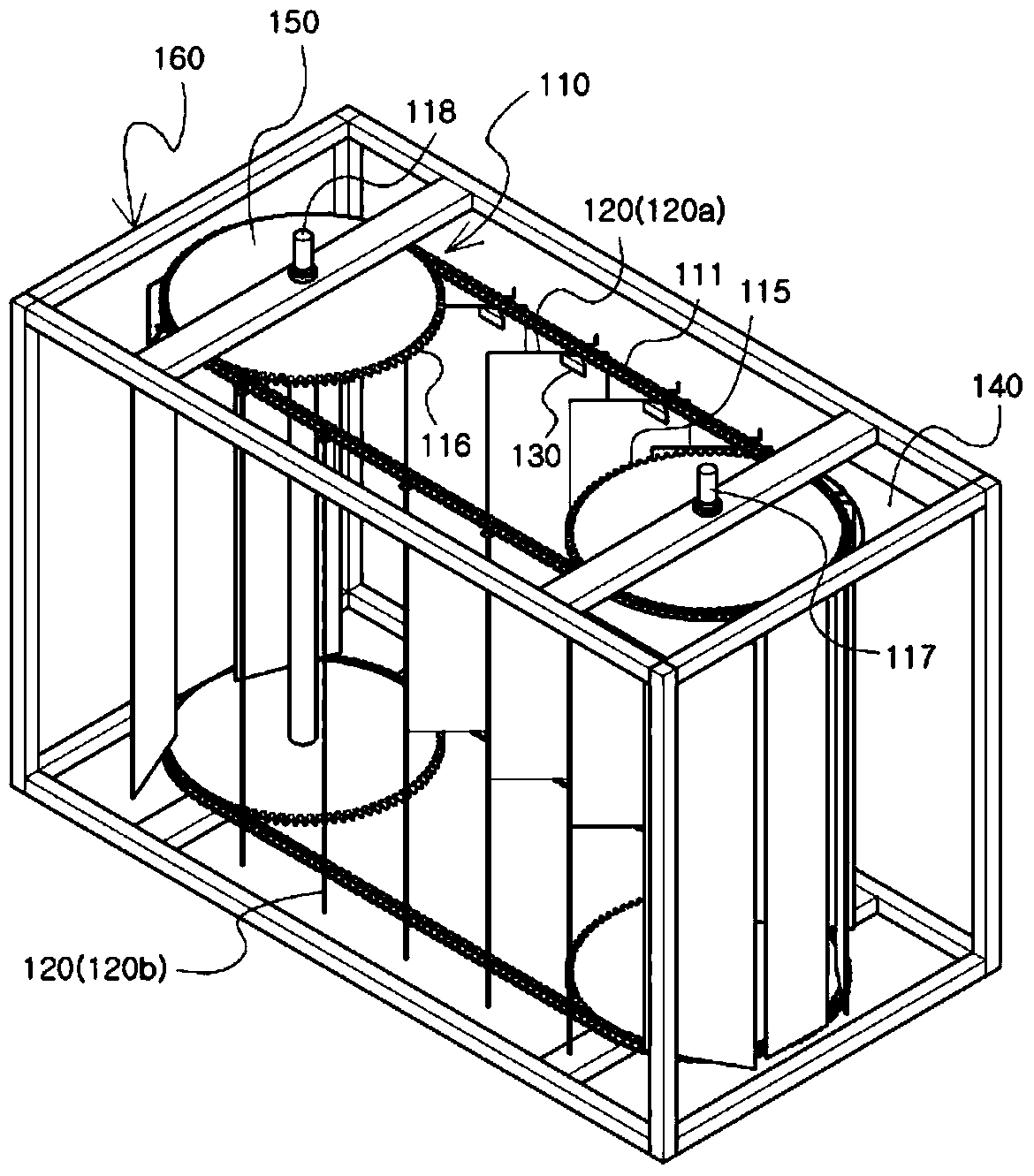
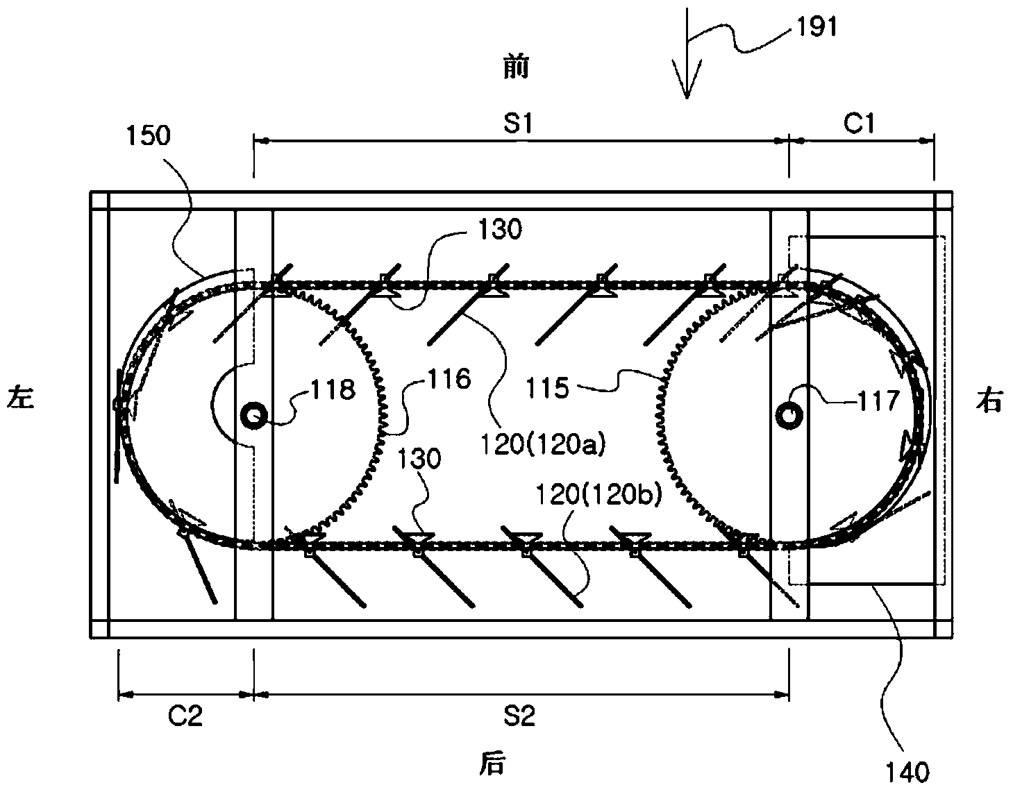
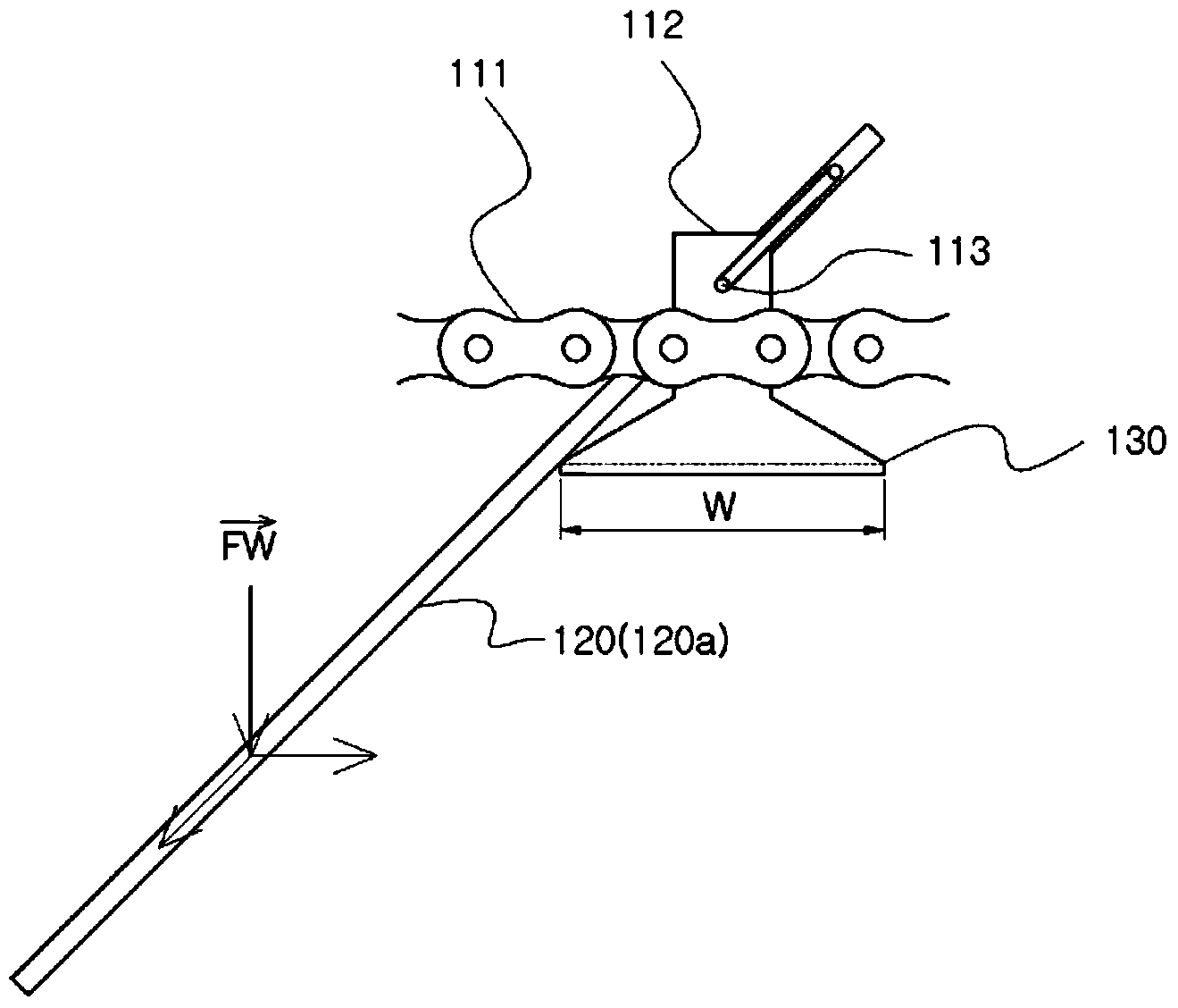
[0026] Such as figure 1 as well as figure 2 As shown, according to the power generation device using flowing water according to the first embodiment of the present invention, the chain of the chain circulation device 110 is provided with a plurality of blades 120 at predetermined intervals, and the chain circulation device 110 is formed with a first chain for the chain 111 to move linearly. A straight line section S1 and a second straight line section S2, when the blade 120 installed on the chain circulation device 110 is immersed in water, the water passes through the blade 120a of the first straight line section S1 and then passes through the blade 120b of the second straight line section S2 , the blade 120 is locked to the stopper 130 of the chain 111, and the blade 120a of the first straight line section S1 and the blade 120b of the second straight...


PUM


Abstract

The present invention relates to a power generating apparatus using flowing water, which converts the energy from the flow speed of the water for generating power to the rotational driving force of a rotating shaft, wherein a plurality of blades (120) are mounted at a certain distance apart from each other on a chain of a chain circulating device (110), a first straight section (S1) and a second straight section (S2) in which the chain (111) moves in a straight line are formed on the chain circulating device (110), the blades (120) mounted on the chain circulating device (110) are immersed in water, water passes through the blades (120a) in the first straight section (S1) and then passes through the blades (120b) in the second straight section (S2), the blades (120) are caught on a stopper (130) provided on the chain (111) so that the blades (120a) in the first straight section (S1); and the blades (120b) in the second straight section (S2) are maintained in an oblique line with respect to the chain (111), a first and second direction adjusting device (140 and 150) are arranged in a first and second curved section (C1 and C2) at which the chain (111) of the chain circulating device (110) passes sprockets (115 and 116), the oblique directions of the blades (120a) in the first straight section (S1) and the blades (120b) in the second straight section (S2) are arranged in mutual opposition by means of the first and second direction adjusting devices (140 and 150), the energy from the flow speed of water changes the circulating power of the chain (111) by means of the blades (120a) in the first straight section (S1) and the blades (120b) in the second straight section (S2), the sprockets (115 and 116) are driven by the chain (111), and the sprockets (115 and 116); drive rotating shafts (117 and 118) so that a rotational force is generated at the rotating shafts (117 and 118).

Description

technical field [0001] The present invention relates to a power generation device using flowing water that converts the flow velocity energy of water into rotational power of a rotating shaft for power generation. Blades are arranged so that the flow velocity energy of water is converted into chain circulation power through the blades, and the chain wheel is driven by the orbital motion of the chain, and the power generation device using flowing water that can obtain rotational power from the rotating shaft through the chain wheel. Background technique [0002] Korean Laid-Open Patent No. 10-2009-52309 (published on May 25, 2009) discloses "a flow rate power generation device that utilizes the force of the flow rate on water and in water". [0003] The flow velocity generating device using the flow velocity multiplier on the water and in the water is provided with a pair of rollers spaced apart from the side by a predetermined distance on the two side ends of the floating bo...

Claims


Application Information

Patent Timeline
IPC IPC(8): F03B17/06F03B9/00
CPCF03B17/064Y02E10/28F03B17/066B63B2035/4466Y02E10/30Y02E10/20F03B17/06F03B9/00
Inventor 韩荣泰
Owner 韩荣泰
Why Eureka
Try Eureka